241: Difference between revisions
No edit summary |
No edit summary |
||
| (5 intermediate revisions by 2 users not shown) | |||
| Line 1: | Line 1: | ||
{{ | {{Instrument Sidebar | ||
|class=Controller | |||
summary=Programmer | | |manufacturer=Tektronix | ||
image=Tek241-axo.jpg | | |model=241 | ||
caption=Tektronix 241 front| | |summary=Programmer | ||
introduced=1967 | | |image=Tek241-axo.jpg | ||
discontinued=1978(?) | | |caption=Tektronix 241 front | ||
|introduced=1967 | |||
manuals= | |discontinued=1978(?) | ||
* [ | |designers= | ||
* [[Media:Tek 241 fcp jan 1969.pdf]] | |manuals= | ||
* [[Media:070-0809-00.pdf|Tektronix 241 Manual]] (PDF) | |||
* [[Media:Tek 241 fcp jan 1969.pdf|Tektronix 241 Factory Calibration Procedure, January 1969]] | |||
}} | }} | ||
The '''Tektronix 241''' is a control unit for the Tektronix [[230]]/[[568]]. It is capable of controlling all programmable aspects of the 230 and compatible sampling plugins ([[3T5]], [[3T6]], [[3S5]], [[3S6]]). | The '''Tektronix 241''' is a control unit for the Tektronix [[230]]/[[568]]. It is capable of controlling all programmable aspects of the 230 and compatible sampling plugins ([[3T5]], [[3T6]], [[3S5]], [[3S6]]). | ||
| Line 23: | Line 24: | ||
The 241 was last mentioned in the 1978 catalog. | The 241 was last mentioned in the 1978 catalog. | ||
== | {{MissingSpecs}} | ||
==See Also== | |||
* [[012-0131-00|012-0131-00 Interconnecting Cable]] | |||
==Links== | |||
{{Documents|Link=241}} | |||
==Pictures== | ==Pictures== | ||
Latest revision as of 07:08, 16 November 2023

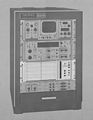
The Tektronix 241 is a control unit for the Tektronix 230/568. It is capable of controlling all programmable aspects of the 230 and compatible sampling plugins (3T5, 3T6, 3S5, 3S6).
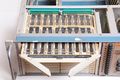
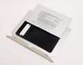
The 241 stores up to 15 programs on diode matrix cards. Each card represents one state of the entire test rig. Cards may be rearranged, and there is room inside the unit for an additional 15 cards (for storage only). Programming is done by arranging diodes to select settings or BCD values, as shown on the silkscreening of the card. Each program is 159 bits, including 14 spares for control of other equipment, such as choppers or multiplexers.
Programs may be selected manually, or automatically sequenced. The sequence can be set to stop when one or more of the programmable limit conditions is met via the 230.
Four cables connect J201, J202, J203 and J204 on the 241 to J201, J202, 203 and J204 on the 230 for the purpose of remotely controlling the 230. Two cables connect J214 and J224 on the 241 to J214 and J224 on the 568 for the purpose of controlling programmable vertical and horizontal plug-ins. Cables are type 012-0131-01 for J204 and 012-0131-00 for others. J204 carries some higher speed signals, while the others carry only control logic.
The 241 does not have a power supply; it is powered from the 230 via J204. The 241 was last mentioned in the 1978 catalog.
Key Specifications
- please add
See Also
Links
Documents Referencing 241
| Document | Class | Title | Authors | Year | Links |
|---|---|---|---|---|---|
| Service scope dec 1968 ocr.pdf | Article | Digital Systems Come of Age | John Bowne | 1968 | 3T5 • 3T6 • 3S5 • 3S6 • S-1 • S-2 • S-3 • S-4 • 568 • 230 • 240 • 241 • 250 |
| Tekscope 1970 V2 N4 Aug 1970.pdf | Article | Automated Measurement Systems | 1970 | S-3150 • 568 • 230 • S-3110 • 241 • 240 |
Pictures
-
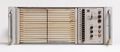
Front
-
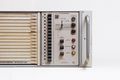
Front Detail
-
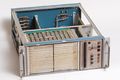
Cover Removed
-

Rear
-

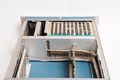
Top
-
Interior
-
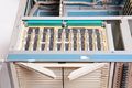
Card Being Removed
-
Card Being Removed
-
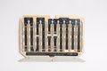
Programming Card
-
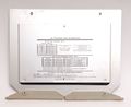
Information Card
-
Information Card Open
-
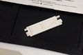
Diode Tool
-
Highlighted in S3310
-
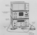
Benchtop Configuration
-
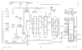
Block diagram


