2A60: Difference between revisions
No edit summary |
No edit summary |
||
| (6 intermediate revisions by 3 users not shown) | |||
| Line 1: | Line 1: | ||
{{Plugin Sidebar | {{Plugin Sidebar | ||
|manufacturer=Tektronix | |||
summary=1 MHz amplifier | | |series=560-series scopes | ||
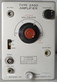
image=Tek 2a60 | |type=2A60 | ||
caption= 2A60 front view | | |summary=1 MHz amplifier plug-in | ||
introduced=1962 | | |image=Tek 2a60 front.jpeg | ||
discontinued=(?) | |caption=2A60 front view | ||
|introduced=1962 | |||
manuals= | |discontinued=(?) | ||
* [ | |manuals= | ||
* [[Media:Tek type 60 irb.pdf|Tektronix Type 60/2A60 Instrument Reference Book (OCR | * [[Media:070-263.pdf|Tektronix 2A60 Manual]] | ||
* [[Media:Tek type 60 irb.pdf|Tektronix Type 60/2A60 Instrument Reference Book]] (OCR) | |||
}} | }} | ||
The '''Tektronix 2A60''' is a 1 MHz, single-channel amplifier plug-in for [[560-series scopes]]. | The '''Tektronix 2A60''' is a 1 MHz, single-channel amplifier plug-in for [[560-series scopes]]. | ||
It was designated "Type 60" before being renamed 2A60 at serial number 820. | It was designated "Type 60" before being renamed 2A60 at serial number 820. | ||
The V/div positions of the 2A60 are somewhat unusual among Tektronix plug-ins. | The V/div positions of the 2A60 are somewhat unusual among Tektronix plug-ins. | ||
Most plug-ins use the | Most plug-ins use the 1−2−5 scale factors, e.g., 10 mV/div, 20 mV/div, 50 mV/div, 100 mV/div, etc. | ||
The 2A60's V/div positions are multiples of ten: 50 mV/div, 500 mV/div, 5 V/div, 50 V/div. | The 2A60's V/div positions are multiples of ten: 50 mV/div, 500 mV/div, 5 V/div, 50 V/div. | ||
This unusual feature was presumably a cost-cutting measure. | This unusual feature was presumably a cost-cutting measure. | ||
| Line 22: | Line 23: | ||
(The [[59|Type 59]] was even cheaper, at half the price of the 2A60.) | (The [[59|Type 59]] was even cheaper, at half the price of the 2A60.) | ||
The 2A60 is similar to the [[3A75]], but the 3A75 has the standard | The 2A60 is similar to the [[3A75]], but the 3A75 has the standard 1−2−5 V/div positions and 4 MHz bandwidth. | ||
The linearization trick of diodes bypassing the cathode resistor (discussed | The linearization trick of diodes bypassing the cathode resistor (discussed below) is also used in the 3A75. | ||
In the [[Tek_Catalogs|1963 Tektronix catalog]], both models were listed. | In the [[Tek_Catalogs|1963 Tektronix catalog]], both models were listed. The 3A75 was 1.7× the cost of the 2A60. | ||
The 3A75 was 1.7× the cost of the 2A60. | |||
{{BeginSpecs}} | {{BeginSpecs}} | ||
| Line 33: | Line 33: | ||
{{Spec | Deflection | 50 mV, 500 mV, 5 V or 50 V per division, plus variable adjustment }} | {{Spec | Deflection | 50 mV, 500 mV, 5 V or 50 V per division, plus variable adjustment }} | ||
{{EndSpecs}} | {{EndSpecs}} | ||
==Links== | |||
{{Documents|Link=2A60}} | |||
==Internals== | ==Internals== | ||
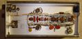
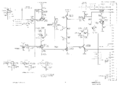
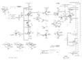
The input signal passes through a compensated attenuator and then into the input amplifier, a differential | The input signal passes through a compensated attenuator and then into the input amplifier, a differential amplifier formed from two [[6AU6]] pentodes. | ||
amplifier formed from two [[6AU6]] pentodes. The differential signal is then applied to a cathode-follower | The differential signal is then applied to a cathode-follower stage which drives the output stage. | ||
stage which drives the output stage. | |||
The output stage is a differential amplifier formed from both halves of a [[6DJ8]] dual-triode. | The output stage is a differential amplifier formed from both halves of a [[6DJ8]] dual-triode. | ||
To help linearize the output stage when it is making large positive or negative excursions, | To help linearize the output stage when it is making large positive or negative excursions, | ||
a pair of germanium diodes is placed in parallel with the resistor that connects the cathodes of output triodes. | a pair of germanium diodes is placed in parallel with the resistor that connects the cathodes of output triodes. | ||
The effect is that when the signal swings far in either direction, the gain degeneration (negative feedback) | The effect is that when the signal swings far in either direction, the gain degeneration (negative feedback) is reduced. | ||
is reduced. This helps keep gain stable across the range of signal voltages. | This helps keep gain stable across the range of signal voltages. | ||
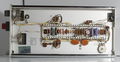
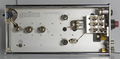
==Pictures== | ==Pictures== | ||
<gallery> | <gallery> | ||
Tek 2a60 front.jpeg | |||
Tek 2a60 front4.jpg | Tek 2a60 front4.jpg | ||
Tek 2a60 front.jpg | Tek 2a60 front.jpg | ||
| Line 61: | Line 64: | ||
</gallery> | </gallery> | ||
==Components== | |||
{{Parts|2A60}} | |||
[[Category:560 series plugins]] | [[Category:560 series plugins]] | ||
Latest revision as of 05:50, 29 November 2023

The Tektronix 2A60 is a 1 MHz, single-channel amplifier plug-in for 560-series scopes. It was designated "Type 60" before being renamed 2A60 at serial number 820.
The V/div positions of the 2A60 are somewhat unusual among Tektronix plug-ins. Most plug-ins use the 1−2−5 scale factors, e.g., 10 mV/div, 20 mV/div, 50 mV/div, 100 mV/div, etc. The 2A60's V/div positions are multiples of ten: 50 mV/div, 500 mV/div, 5 V/div, 50 V/div. This unusual feature was presumably a cost-cutting measure.
The 2A60 was the one of the least expensive amplifier plug-ins for 560-series scopes. (The Type 59 was even cheaper, at half the price of the 2A60.)
The 2A60 is similar to the 3A75, but the 3A75 has the standard 1−2−5 V/div positions and 4 MHz bandwidth. The linearization trick of diodes bypassing the cathode resistor (discussed below) is also used in the 3A75.
In the 1963 Tektronix catalog, both models were listed. The 3A75 was 1.7× the cost of the 2A60.
Key Specifications
| Bandwidth | 1 MHz |
|---|---|
| Rise time | 350 ns |
| Deflection | 50 mV, 500 mV, 5 V or 50 V per division, plus variable adjustment |
Links
Documents Referencing 2A60
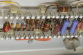
Internals
The input signal passes through a compensated attenuator and then into the input amplifier, a differential amplifier formed from two 6AU6 pentodes. The differential signal is then applied to a cathode-follower stage which drives the output stage.
The output stage is a differential amplifier formed from both halves of a 6DJ8 dual-triode. To help linearize the output stage when it is making large positive or negative excursions, a pair of germanium diodes is placed in parallel with the resistor that connects the cathodes of output triodes. The effect is that when the signal swings far in either direction, the gain degeneration (negative feedback) is reduced. This helps keep gain stable across the range of signal voltages.
Pictures
-

-
-
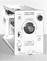
-
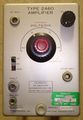
-

-
-
Schematic (early)
-
Schematic (late)
-
-
-
diodes for linearization


