485: Difference between revisions
No edit summary |
No edit summary |
||
| (20 intermediate revisions by 4 users not shown) | |||
| Line 1: | Line 1: | ||
{{Oscilloscope Sidebar |manufacturer=Tektronix | | {{Oscilloscope Sidebar | ||
series=400-series scopes | | |manufacturer=Tektronix | ||
model=485| | |series=400-series scopes | ||
image=Tektronix 485 oscilloscope2.jpg| | |model=485 | ||
caption=Tektronix 485| | |image=Tektronix 485 oscilloscope2.jpg | ||
introduced=1972 | | |caption=Tektronix 485 | ||
discontinued=1986 | | |introduced=1972 | ||
summary=350 MHz portable scope| | |discontinued=1986 | ||
manuals= | |summary=350 MHz portable scope | ||
* [ | |designers=John Addis;Wink Gross;Gene Andrews;Glenn Bateman;Ron Peltola;Bob Firth;Murlan Kaufman;Bob White;Keith Taylor;Dick Troberg | ||
* [[Media:Tek-485 OCR.pdf|Tektronix 485 Manual ( | |manuals= | ||
* [ | * [[Media:070-1193-00.pdf|Tektronix 485 Manual]] (bad-OCR) | ||
* [[Media:Tek 485 cal proc.pdf|Tektronix 485 Calibration Procedure | * [[Media:Tek-485 OCR.pdf|Tektronix 485 Manual]] (OCR) | ||
* [http://bama.edebris.com/download/tek/485/tek-485.pdf Tektronix 485 Manual] | |||
* [[Media:Tek 485 cal proc.pdf|Tektronix 485 Calibration Procedure]] | |||
}} | }} | ||
The '''Tektronix 485''' is a dual-trace, portable analog oscilloscope with a maximum | The '''Tektronix 485''' is a dual-trace, portable analog oscilloscope with a maximum | ||
bandwidth of 350 MHz. | bandwidth of 350 MHz, [[introduced in 1972|introduced in March of 1972]]. | ||
The impedance of the inputs can be set individually to 50 Ω or 1 MΩ. | |||
The scope achieves its maximum bandwidth when the inputs are in 50 Ω mode. | The scope achieves its maximum bandwidth when the inputs are in 50 Ω mode. | ||
A distinguishing feature – at least in a portable oscilloscope of its period – is the Alternate Horizontal Mode. | A distinguishing feature – at least in a portable oscilloscope of its period – is the Alternate Horizontal Mode. | ||
In this mode, the B timebase is shown in a separate full-width scan, as opposed to the more common Mixed Mode, | In this mode, the B timebase is shown in a separate full-width scan, as opposed to the more common Mixed Mode, where the B timebase is shown on the same line as the A timebase, after the delay time. | ||
where the B timebase is shown on the same line as the A timebase, after the delay time | |||
The [[465]], which was introduced after the 485, only received this feature in its "B" incarnation (465B). | The [[465]], which was introduced after the 485, only received this feature in its "B" incarnation (465B). | ||
Variant 485-1 omits the "A EXT Trigger display", as does variant 485-2 which additionally only has 50 Ω inputs. | |||
[[John Addis]] was project leader for the vertical section, assisted by [[Wink Gross]]. | |||
[[Glenn Bateman]], [[Ron Peltola]] and [[Bob Firth]] designed the low- and high-impedance attenuators. | |||
[[Murlan Kaufman]] was project leader for the horizontal and logic systems and designed the trigger generator. | |||
[[Bob White]] designed the trigger amplifier and external trigger view circuits. | |||
[[Keith Taylor]] did the work on the fast sweeps, the horizontal and the Z-axis amplifiers. | |||
[[Dick Troberg]] designed the high efficiency power supply system. | |||
{{BeginSpecs}} | {{BeginSpecs}} | ||
{{Spec | Input Impedance | 50 Ω / 1 MΩ // 20 pF }} | {{Spec | Input Impedance | 50 Ω / 1 MΩ // 20 pF }} | ||
{{Spec | Rise time | {{Spec | Rise time | 1 ns (50 Ω) / 1.4 ns (1 MΩ) }} | ||
{{Spec | Bandwidth | {{Spec | Bandwidth | 350 MHz (50 Ω) / 250 MHz (1 MΩ) }} | ||
{{Spec | Deflection | 5 mV/div to 5 V/div in 1−2−5 sequence, 2% accuracy }} | {{Spec | Deflection | 5 mV/div to 5 V/div in 1−2−5 sequence, 2% accuracy }} | ||
{{Spec | Time Base | {{Spec | Time Base | 1 ns/div to 0.5 s/div in 1−2−5 sequence}} | ||
{{Spec | CRT | [[154-0652-00]] and [[154-0652-05]], 21 kV acceleration, 8 × 10 divisions (0.8 cm/div)}} | |||
{{Spec | Weight | 9.3 kg (21.5 lb) }} | |||
{{Spec | Power | AC 90–136 or 180–272 V, 48–440 Hz, 60 W @ 115V }} | |||
{{EndSpecs}} | {{EndSpecs}} | ||
==Links== | ==Links== | ||
* [ | * [[Gene Andrews]], ''A nanosecond portable oscilloscope''. In [[Media:Tekscope_1972_V4_N2_Mar_1972.pdf|Tekscope Vol.4 No.2, March 1972]], p.2+. | ||
* [https://www.amplifier.cd/Test_Equipment/Tektronix/Tektronix_other/485.html Tek 485 @ amplifier.cd] | |||
* [https://youtube.com/watch?v=7Qg6ory3L8Y 485 troubleshooting] @ YouTube | * [https://youtube.com/watch?v=7Qg6ory3L8Y 485 troubleshooting] @ YouTube | ||
* [https://www.youtube.com/watch?v=P56MyUK3n18 485 Restoration and Repair] @ Zenwizard Studios YouTube | |||
* [https://www.youtube.com/watch?v=95rlRAlRT5k 485 Power Supply and Tube Alignment] @ Zenwizard Studios YouTube | |||
* [https://www.youtube.com/watch?v=mJa5jap968w 485 Horizontal Alignment] @ Zenwizard Studios YouTube | |||
* [https://www.youtube.com/watch?v=lVsLMrCnOK4 485 Vertical and Trigger alignment] @ Zenwizard Studios YouTube | |||
==Prices== | |||
{| class="wikitable" | |||
|- | |||
! Year | |||
! 1972 | |||
! 1973 | |||
! 1976 | |||
! 1980 | |||
! 1982 | |||
! 1986 | |||
|- | |||
! Catalog Price | |||
|align=right| $4,200 | |||
|align=right| $4,200 | |||
|align=right| $4,550 | |||
|align=right| $6,035 | |||
|align=right| $6,975 | |||
|align=right| $9,100 | |||
|- | |||
! In 2023 Dollars | |||
|align=right| $30,900 | |||
|align=right| $29,100 | |||
|align=right| $24,600 | |||
|align=right| $22,500 | |||
|align=right| $22,200 | |||
|align=right| $25,600 | |||
|} | |||
== | ==Internals== | ||
The 485 includes a switching power supply and uses [[155-0078-00|custom integrated circuits]] for most of the gain blocks. Triggering uses [[tunnel diodes]]. | |||
==Pictures== | ==Pictures== | ||
===External=== | |||
<gallery> | <gallery> | ||
Tek 485 trace.jpg | Tek 485 trace.jpg | ||
Tek_485_Trace.jpeg | |||
Tektronix 485 oscilloscope2.jpg | Tektronix 485 oscilloscope2.jpg | ||
Tek 485.jpg | Tek 485.jpg | ||
Tek 485 front2.jpg | Tek 485 front2.jpg | ||
Tek 485 front.jpg | Tek 485 front.jpg | ||
Tek_485-rear.jpeg | |||
Tek 485 rear.jpg | Tek 485 rear.jpg | ||
Tektronix 485 oscilloscope5.jpg | Tektronix 485 oscilloscope5.jpg | ||
Tek 485 tq.jpg | Tek 485 tq.jpg | ||
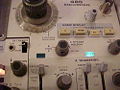
Tek_485_A-Ext-Trig-Display.jpeg | Time base A, External trigger display switch | |||
USA Tektronix 485 Inside1.jpg | USA Tektronix 485 Inside1.jpg | ||
</gallery> | |||
===Internals=== | |||
<gallery> | |||
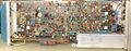
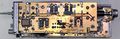
Tek_485-Top.jpeg | Top, Horizontal Amp board | |||
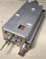
Tek_485-Underside.jpeg | Underside, Power supply, A-Trig board | |||
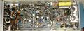
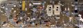
Tek_485-RHS.jpeg | LHS, Vertical Amp board | |||
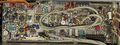
Tek_485-LHS.jpeg | RHS, Sweep/Inverter board | |||
Tek_485-A-Trigger-bd.jpeg | A-Trigger board | |||
Tek_485-attenuator-Assy.jpeg | Vertical attenuator Assy | |||
Tek 485-attenuator-Inside.jpeg | Vertical attenuator Assy, 50Ω Board | |||
Tek_485-Hi-Z-attenuator-bd.jpeg | Vertical attenuator Assy, Hi-Z Board | |||
</gallery> | </gallery> | ||
{{ | ==Components== | ||
{{Parts|485}} | |||
[[Category:400 series scopes]] | [[Category:400 series scopes]] | ||
Latest revision as of 15:30, 27 October 2023

The Tektronix 485 is a dual-trace, portable analog oscilloscope with a maximum bandwidth of 350 MHz, introduced in March of 1972.
The impedance of the inputs can be set individually to 50 Ω or 1 MΩ. The scope achieves its maximum bandwidth when the inputs are in 50 Ω mode.
A distinguishing feature – at least in a portable oscilloscope of its period – is the Alternate Horizontal Mode. In this mode, the B timebase is shown in a separate full-width scan, as opposed to the more common Mixed Mode, where the B timebase is shown on the same line as the A timebase, after the delay time.
The 465, which was introduced after the 485, only received this feature in its "B" incarnation (465B).
Variant 485-1 omits the "A EXT Trigger display", as does variant 485-2 which additionally only has 50 Ω inputs.
John Addis was project leader for the vertical section, assisted by Wink Gross. Glenn Bateman, Ron Peltola and Bob Firth designed the low- and high-impedance attenuators. Murlan Kaufman was project leader for the horizontal and logic systems and designed the trigger generator. Bob White designed the trigger amplifier and external trigger view circuits. Keith Taylor did the work on the fast sweeps, the horizontal and the Z-axis amplifiers. Dick Troberg designed the high efficiency power supply system.
Key Specifications
| Input Impedance | 50 Ω / 1 MΩ // 20 pF |
|---|---|
| Rise time | 1 ns (50 Ω) / 1.4 ns (1 MΩ) |
| Bandwidth | 350 MHz (50 Ω) / 250 MHz (1 MΩ) |
| Deflection | 5 mV/div to 5 V/div in 1−2−5 sequence, 2% accuracy |
| Time Base | 1 ns/div to 0.5 s/div in 1−2−5 sequence |
| CRT | 154-0652-00 and 154-0652-05, 21 kV acceleration, 8 × 10 divisions (0.8 cm/div) |
| Weight | 9.3 kg (21.5 lb) |
| Power | AC 90–136 or 180–272 V, 48–440 Hz, 60 W @ 115V |
Links
- Gene Andrews, A nanosecond portable oscilloscope. In Tekscope Vol.4 No.2, March 1972, p.2+.
- Tek 485 @ amplifier.cd
- 485 troubleshooting @ YouTube
- 485 Restoration and Repair @ Zenwizard Studios YouTube
- 485 Power Supply and Tube Alignment @ Zenwizard Studios YouTube
- 485 Horizontal Alignment @ Zenwizard Studios YouTube
- 485 Vertical and Trigger alignment @ Zenwizard Studios YouTube
Prices
| Year | 1972 | 1973 | 1976 | 1980 | 1982 | 1986 |
|---|---|---|---|---|---|---|
| Catalog Price | $4,200 | $4,200 | $4,550 | $6,035 | $6,975 | $9,100 |
| In 2023 Dollars | $30,900 | $29,100 | $24,600 | $22,500 | $22,200 | $25,600 |
Internals
The 485 includes a switching power supply and uses custom integrated circuits for most of the gain blocks. Triggering uses tunnel diodes.
Pictures
External
-

-

-

-

-
-

-

-

-
-

-
Time base A, External trigger display switch
-


Internals
-
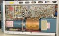
Top, Horizontal Amp board
-
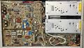
Underside, Power supply, A-Trig board
-
LHS, Vertical Amp board
-
RHS, Sweep/Inverter board
-
A-Trigger board
-
Vertical attenuator Assy
-
Vertical attenuator Assy, 50Ω Board
-
Vertical attenuator Assy, Hi-Z Board


Components
Some Parts Used in the 485
| Part | Part Number(s) | Class | Description | Used in |
|---|---|---|---|---|
| 148-0034-01 | 148-0034-01 | Discrete component | miniature DPDT relay | 485 • 7A12 |
| 155-0011-00 | 155-0011-00 | Monolithic integrated circuit | clock and chop blanking | 485 • 7313 • 7403N • R7403N • 7503 • 7504 • 7514 • 7603 • AN/USM-281C • 7613 • 7623 • 7623A • 7633 • 7704 • R7704 • 7704A • 7834 • 7844 • 7854 • 7904 • 7904A • R7903 • R7912 • 7912AD • 7912HB • 7934 • 7104 • R7103 • AN/USM-281C |
| 155-0012-00 | 155-0012-00 | Monolithic integrated circuit | Z Axis Logic | 485 • 7504 • 7514 • 7704 • R7704 • 7704A • 7834 • 7844 • 7854 • 7904 • R7903 • 7904A • R7912 • 7934 • 7912AD • 7912HB • 7104 • R7103 |
| 155-0049-00 | 155-0049-00 • 155-0049-01 • 155-0049-02 | Monolithic integrated circuit | sweep control with lockout | 335 • 464 • 465 • 466 • 475 • 475A • 475M • 485 • 5B31 • 5B40 • 5B52 • 5B42 • 5B44 • 7B53A • 7B80 • 7B85 • 7B87 • 7B92A • 7B90P • 7B10 • 7B15 • SC502 • 7B42N • AN/USM-281C • 067-0657-00 |
| 155-0064-00 | 155-0064-00 | Hybrid integrated circuit | vertical output amplifier | 7834 • 7854 • 7904 • R7903 • 7912AD • 485 • PG502 |
| 155-0067-02 | 155-0067-00 • 155-0067-02 • 155-0067-03 | Monolithic integrated circuit | SMPS controller | 7704A • 7834 • 7844 • 7854 • 7904 • R7903 • 7904 • 7904A • 7934 • R7912 • 7912AD • 7912HB • 7934 • 7104 • R7103 • 308 • 434 • 485 • 690 • P7001 |
| 155-0076-00 | 155-0076-00 | Monolithic integrated circuit | input protection and probe logic | 465 • 485 • 7A29 • 7A29P • 11A52 • 11A71 • 11A72 • SCD1000 |
| 155-0078-00 | 155-0078-xx • 155-0273-00 • 155-0274-00 | Monolithic integrated circuit | broadband amplifier | 464 • 465 • 466 • 468 • 475 • 475A • 475M • 485 • 7834 • 7844 • 7854 • 7904 • R7903 • R7912 • 7912AD • 7912HB • 7104 • 7A16A • 7A16P • 7A24 • 7A26 • 7A42 • 067-0587-01 • 067-0680-00 • AM503 • PG502 • PG508 • DC510 • DC5010 • FG5010 |
| SMTD994 | 152-0177-01 | Discrete component | 10 mA, 2 pF tunnel diode | 067-0587-01 • 067-0580-00 • 3T5 • 3T6 • 485 • 5S14N • 7D14 • 7T11 • 7T11A • S-53 |
| SMTD998 | 152-0177-02 | Discrete component | 10 mA, 2 pF tunnel diode | 067-0681-01 • 485 • 7B92 • 7B92A |