7104: Difference between revisions
No edit summary |
|||
| (47 intermediate revisions by 3 users not shown) | |||
| Line 1: | Line 1: | ||
{{Oscilloscope Sidebar| | {{Oscilloscope Sidebar | ||
|manufacturer=Tektronix | |||
image=Tek7104-front.jpg| | |series=7000-series scopes | ||
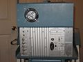
caption=Tektronix 7104, front view| | |model=7104 | ||
introduced=1978 | | |image=Tek7104-front.jpg | ||
discontinued=1990 | | |caption=Tektronix 7104, front view | ||
summary=1 GHz | |introduced=1978 | ||
manuals= | |discontinued=1990 | ||
* [ | |summary=1 GHz mainframe with MCP CRT | ||
|designers=Val Garuts;Gene Andrews;Hans Springer;John Addis;Wink Gross;Art Metz;Aris Silzars;Conrad Odenthal;Dave Morgan; | |||
|manuals= | |||
* [[Media:070-2314-00.pdf|Tektronix 7104 Manual with Options]] (OCR) | |||
* [[Media:7104_maintenance.pdf | 7104 maintenance - Tek-internal introduction for technicians]] | |||
''Other Information'' | |||
* [[Media:Dennis Tillman 7104-7854 SMPS Dummy Load.pdf | Dummy load for troubleshooting 7854 and 7104 SMPS (Dennis Tillman) ]] | |||
}} | }} | ||
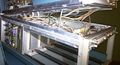
The '''Tektronix 7104''' is a 1 GHz, non-storage 7000-series oscilloscope mainframe that takes two [[7000-series_plug-ins#Vertical plug-ins|7000-series vertical plug-ins]] and two [[7000-series_plug-ins#Horizontal plug-ins|7000-series horizontal plug-ins]]. It was introduced in 1978. There is also a rack-mount version, the [[R7103]], albeit with only one horizontal bay. | The '''Tektronix 7104''' is a 1 GHz, non-storage 7000-series oscilloscope mainframe that takes two [[7000-series_plug-ins#Vertical plug-ins|7000-series vertical plug-ins]] and two [[7000-series_plug-ins#Horizontal plug-ins|7000-series horizontal plug-ins]]. It was introduced in 1978. There is also a rack-mount version, the [[R7103]], albeit with only one horizontal bay. | ||
The scope employs a [[micro-channel plate]] (MCP) CRT design to get good screen intensity at high sweep speeds with moderate acceleration voltage. | The scope employs a [[micro-channel plate]] (MCP) CRT design to get good screen intensity at high sweep speeds with moderate acceleration voltage. The benefit is especially noticeable at low repetition rates. | ||
The high speed necessitated using [[distributed deflection plates]] also for the horizontal deflection system, which reaches a | The high horizontal speed necessitated using [[distributed deflection plates]] also for the horizontal deflection system, which reaches a bandwidth of 350 MHz. | ||
bandwidth of 350 MHz. Option 2 adds a horizontal delay line to make the high horizontal bandwidth available for X-Y mode | Option 2 adds a horizontal delay line to make the high horizontal bandwidth available for X-Y mode at a phase shift of <2° up to 50 MHz, nullable at any frequency up to 250 MHz. | ||
at a phase shift of <2° up to 50 MHz, nullable at any frequency up to 250 MHz. | |||
The [[7A29]] 1 GHz vertical amplifier and the [[7B15]]/[[7B10]] time base pair were introduced along with the 7104 to match the system bandwidth. | The [[7A29]] 1 GHz vertical amplifier and the [[7B15]]/[[7B10]] time base pair were introduced along with the 7104 to match the system bandwidth. | ||
[[Val Garuts]] was the initial project leader. [[Gene Andrews]] took over the project lead about half way through the seven year development. [[John Addis]] was the Project Engineer for the vertical system. He designed the 7A29 plugin and its [[H500]] and [[H476]] ICs (the latter was also used in the 7104 mainframe). [[Wink Gross]] designed the 7104 main vertical amplifier including the channel switch, the main vertical output amplifier and its [[H477]] IC. [[Dave Morgan]] designed the mainframe horizontal amplifier, and [[Art Metz]] designed the Z axis system. [[Dennis Hall]] was the project leader for the CRT. [[Aris Silzars]] designed the vertical deflection plate structure and managed the acquisition of the microchannel plate. [[Conrad Odenthal]] designed the box lens for the CRT. | |||
{{BeginSpecs}} | {{BeginSpecs}} | ||
| Line 35: | Line 42: | ||
* Readout | * Readout | ||
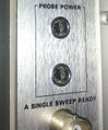
* 2 probe power connectors | * 2 probe power connectors | ||
}} | |||
{{Spec | Options | | |||
* Opt.02 – X-Y Horizontal Compensation | |||
* Opt.03 – EMI modification | |||
}} | }} | ||
{{EndSpecs}} | {{EndSpecs}} | ||
==MCP protection== | ==MCP protection== | ||
The Micro Channel Plate's amplification degrades irreversibly with operation, in proportion to the log of total charge passed per | The Micro Channel Plate's amplification degrades irreversibly with operation, in proportion to the log of total charge passed per display area. | ||
For this reason, continued operation with a steady trace and especially at large beam currents must be avoided. ''The 7104 should '''not''' be used with plug-ins that generate a slow continuous sweep, or vector graphics. This includes [[:Category:7000 series sampling plugins|sampling plug-ins]], [[:Category:7000 series spectrum analyzer plugins|spectrum analyzers]], [[:Category:7000 series logic analyzer plugins|logic analyzers]], and the [[7D20]] digitizer.'' | |||
The 7104 contains a "limited viewing time" circuit to assist with observing this restriction. | |||
At beam currents above 0.2 μA, a yellow indicator illuminates, and the beam will be shut down after 20 minutes. | |||
The limit time drops to two minutes at an average beam current of 2 μA, and also limits the average current to that value. | |||
Single-shot display current is not affected. | |||
Despite this limiter, older instruments often exhibit darkening of the screen around the horizontal center line to some degree (see [[Media:Tek7104-200ps-singleshot-sin1-1g.jpg|screen shot]]). | |||
==Internals== | ==Internals== | ||
| Line 46: | Line 65: | ||
The 7104's amplifiers use a then novel scheme of "feed-beside" compensation ([http://www.google.com/patents/US4132958 US Pat. 4.132.958]) where instead of matching the HF response to the LF response, the LF response is determined by off-the-shelf operational amplifiers in parallel to the high-speed amplifiers, with a number of adjustable R-C time constants to compensate for thermal and other LF effects. The same technique is employed in the [[7A29]] amplifier plug-in. | The 7104's amplifiers use a then novel scheme of "feed-beside" compensation ([http://www.google.com/patents/US4132958 US Pat. 4.132.958]) where instead of matching the HF response to the LF response, the LF response is determined by off-the-shelf operational amplifiers in parallel to the high-speed amplifiers, with a number of adjustable R-C time constants to compensate for thermal and other LF effects. The same technique is employed in the [[7A29]] amplifier plug-in. | ||
===Power Supply=== | |||
The 7104 uses a switch-mode power supply. | |||
Module A23 (schematic page <14>) contains the mains rectifier, base drive circuitry, and power transistors of the inverter (aka, switcher). | |||
These transistors produce a 25 kHz waveform that is fed to the primary of T1310 ([[120-1183-00]]), whose secondaries provide the power for the rest of the scope. | |||
Module A24 (also on schematic page <14>) contains the inverter control circuit and rectifiers for the secondaries of T1310. The inverter control circuit uses the [[155-0067-02]] inverter control IC, which is U1275. | |||
Module A25 (schematic page <15>) contains the low-voltage regulators. | |||
There are independently regulated and current-limited sections for the −50 V, −15 V, +5 V, +15 V and +50 V rails. | |||
Each section has an opamp and a BJT output transistor in emitter-follower configuration. | |||
The opamps need power, too. | |||
To avoid a dependency cycle, the power supplies for the opamps are separate low-current, low-efficiency zener clamps that in no way depend on the −50 V, −15 V, +5 V, +15 V or +50 V regulators. | |||
The power supplies for the opamps produce −22 V, −5.6 V, +5.6 V, and +22 V. | |||
To avoid exceeding the opamps' limit of 30 V total rail voltage, each opamp either gets −22 V and +5.6 V, or −5.6 V and +22 V, depending on whether it needs more output swing in the positive or negative direction. | |||
The +50 V section produces the reference voltage ("50VS") for the other sections. It uses a 9 V zener diode, VR1412, as a reference. | |||
The dependency relationship of the supplies is: | |||
* The −50 V, −15 V, +5, and +15 V sections depend on | |||
** the +50 V supply for reference voltage, | |||
** the opamp supplies for to power their opamps, and | |||
** the A24 semi-regulated rectifier outputs | |||
* The +50 V depends on | |||
** the opamp supplies (+22 V and −5.6 V) for to power its opamp, | |||
** the A24 semi-regulated rectifier outputs (−54 and +54 V) | |||
* The opamps supplies depend on | |||
** the A24 semi-regulated rectifier outputs | |||
* The semi-regulated rectifier outputs depend only on mains power to enter tick/burst mode. However, to enter normal mode, a variety of things need to be working properly. | |||
==Prices== | ==Prices== | ||
| Line 63: | Line 113: | ||
|align=right| $29,995 | |align=right| $29,995 | ||
|- | |- | ||
! | ! In 2023 Dollars | ||
|align=right| $ | |align=right| $53,700 | ||
|align=right| $ | |align=right| $63,200 | ||
|align=right| $ | |align=right| $70,500 | ||
|- | |- | ||
!rowspan=2| Mainframe with [[7A29]],<br />7A29 Opt. 04, [[7B15]], [[7B10]] | !rowspan=2| Mainframe with [[7A29]],<br />7A29 Opt. 04, [[7B15]], [[7B10]] | ||
| Line 74: | Line 124: | ||
|align=right| $44,510 | |align=right| $44,510 | ||
|- | |- | ||
! | ! In 2023 Dollars | ||
|align=right| $ | |align=right| $81,000 | ||
|align=right| $ | |align=right| $94,200 | ||
|align=right| $ | |align=right| $104,600 | ||
|- | |- | ||
|} | |} | ||
==Links== | ==Links== | ||
* Hans Springer's 1979 [https://vintagetek.org/breakthroughs-throughout-push-scope-to-1-ghz/ Electronic Design article on the 7104] | |||
* Hans Springer's 1979 [ | |||
* [http://readingjimwilliams.blogspot.com/2011/08/scope-sunday-4.html Reading Jim Williams: Scope Sunday 4] | * [http://readingjimwilliams.blogspot.com/2011/08/scope-sunday-4.html Reading Jim Williams: Scope Sunday 4] | ||
* [http://amplifier.cd/Test_Equipment/Tektronix/Tektronix_7000_series_mainframe/7104.htm Tek 7104 @ amplifier.cd] | * [http://amplifier.cd/Test_Equipment/Tektronix/Tektronix_7000_series_mainframe/7104.htm Tek 7104 @ amplifier.cd] | ||
* [http://www.barrytech.com/tektronix/tek7000/tek7104.html Tek 7104 @ barrytech.com] | * [http://www.barrytech.com/tektronix/tek7000/tek7104.html Tek 7104 @ barrytech.com] | ||
* [https://web.archive.org/web/20110926020847/http://www.oregonlive.com/silicon-forest/index.ssf/2011/09/a_tektronix_oscilloscope_that.html A Tektronix oscilloscope that moved faster than light?] The Oregonian, 23 Sep 2011. (Original no longer accessible, link via archive.org.) | * [https://web.archive.org/web/20110926020847/http://www.oregonlive.com/silicon-forest/index.ssf/2011/09/a_tektronix_oscilloscope_that.html A Tektronix oscilloscope that moved faster than light?] The Oregonian, 23 Sep 2011. (Original no longer accessible, link via archive.org.) | ||
* [http://www.radiomuseum.org/r/tektronix_oscilloscope_mainframe_7104.html Tektronix 7104 @ radiomuseum.org] | |||
{{Documents|Link=7104}} | |||
==Pictures== | ==Pictures== | ||
<gallery> | <gallery> | ||
Tek7104-front.jpg | 7104 front view (operating) | |||
Tek7104-1.jpg | 7104 with camera mounting frame on cart | |||
Tek 7104 front.jpg | Front with empty plug-in bays | |||
Tek 7104 plugin bay.jpg | Plug-in bays | |||
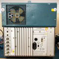
Tek7104-5.jpg | Rear view of 7104 | |||
Tek 7104 rear.jpg | Rear view of 7104 | |||
Tek 7104 probe power.jpg | Probe power outlets | |||
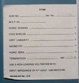
Tek 7104 crtlabel.jpg | CRT label | |||
Tek 7104 crtlabel mono.jpg | CRT label | |||
Tek 7104 crt circuit1.jpg | CRT Circuit | |||
Tek 7104 crt circuit2.jpg | CRT Circuit | |||
Tek 7104 front outputs brightened.jpg | Front outputs | |||
Tek 7104 readout circuit brightened.jpg | Readout board | |||
Tek 7104 right brightened.jpg | Interior right side | |||
Tek7104-hor-and-vert-amp.jpg | 7104 horizontal (top) and vertical (bottom) output amplifiers | |||
Tek 7104 vertamp brightened.jpg | Vertical amplifier | |||
Tek 7104 vertampclose brightened.jpg | Vertical amplifier close-up | |||
Tek 7104 finalvert brightened.jpg | Vertical amplifier, final stage close-up | |||
Tek 7104 vertcrtinterconnect brightened.jpg | Vertical CRT interconnect | |||
Tek 7104 horizamp.jpg | Horizontal amplifier | |||
Tek-7104-horiz-out-and-term.jpg | 7104 horizontal output amplifier, CRT connection and termination of distributed horizontal deflection plates | |||
Tek 7104 rearright brightened.jpg | Rear right (vertical channel switch board and mainframe interconnect) | |||
Tek7104-vert-sw.jpg | Tek7104-vert-sw.jpg | 7104 vertical channel switch board | ||
Tek 7104 channel switch.jpg | 7104 vertical channel switch board | |||
Tek 7104 split.jpg | The upper half of the 7104 can be tilted upward for service. A metal support is included, like on the hood of a car. | |||
</gallery> | </gallery> | ||
===Measurements=== | ===Measurements=== | ||
<gallery> | <gallery> | ||
Tek7104-ristetime-100hz.jpg | Rise time measurement. 150 ps risetime pulse from [[067-0587-02]] at 100 Hz repetition rate. Measured 240 ps (corrected for 150 ps fixture rise time: 190 ps = 1.8 GHz) | |||
Tek7104-ristetime-1000hz.jpg | Rise time measurement as before, 1000 Hz repetition rate at same brightness settings. | |||
Tek7104-200ps-singleshot.jpg | 7104 recording a single shot pulse (from [[067-0587-02]]) at 200 ps/Div. Camera: Nikon D7000, 50 mm f/1.4, ISO 3200, 1/2 s. CRT filter not removed. | |||
Tek7104-200ps-singleshot-sin1-1g.jpg | 7104 recording 1 GHz sine, ''single sweep'' at 500 ps/Div. Camera: Nikon D7000, 50 mm f/1.4, ISO 3200, 1/2 s manually released. CRT filter not removed. CRT amplification loss is evident around the center line. | |||
Tek7104-superluminal-beam.jpg | [https://web.archive.org/web/20110926020847/http://www.oregonlive.com/silicon-forest/index.ssf/2011/09/a_tektronix_oscilloscope_that.html Faster-than-light] beam on 7104? Using a [[067-0587-02]] calibration fixture at maximum amplitude produces this trace spanning 1.2 Div horizontally at 200 ps/Div and 8 Div vertically. Trace length is (1.2² + 8²)<sup>½</sup> × 8.5 mm = 68.8 mm, travelled in 1.2 × 200 ps = 240 ps. Apparent speed is therefore 68.8×10<sup>-3</sup> / 240×10<sup>-12</sup> m/s or 2.86×10<sup>8</sup> m/s. 95.6% c<sub>0</sub> - a '''very''' near miss ... | |||
</gallery> | </gallery> | ||
==Components== | |||
{{Parts|7104}} | |||
{{Custom ICs|7000 series readout system}} | |||
[[Category:7000 series non-storage mainframes]] | [[Category:7000 series non-storage mainframes]] | ||
[[Category:Micro-channel plate CRTs]] | [[Category:Micro-channel plate CRTs]] | ||
Latest revision as of 11:02, 29 January 2024

The Tektronix 7104 is a 1 GHz, non-storage 7000-series oscilloscope mainframe that takes two 7000-series vertical plug-ins and two 7000-series horizontal plug-ins. It was introduced in 1978. There is also a rack-mount version, the R7103, albeit with only one horizontal bay.
The scope employs a micro-channel plate (MCP) CRT design to get good screen intensity at high sweep speeds with moderate acceleration voltage. The benefit is especially noticeable at low repetition rates.
The high horizontal speed necessitated using distributed deflection plates also for the horizontal deflection system, which reaches a bandwidth of 350 MHz. Option 2 adds a horizontal delay line to make the high horizontal bandwidth available for X-Y mode at a phase shift of <2° up to 50 MHz, nullable at any frequency up to 250 MHz.
The 7A29 1 GHz vertical amplifier and the 7B15/7B10 time base pair were introduced along with the 7104 to match the system bandwidth.
Val Garuts was the initial project leader. Gene Andrews took over the project lead about half way through the seven year development. John Addis was the Project Engineer for the vertical system. He designed the 7A29 plugin and its H500 and H476 ICs (the latter was also used in the 7104 mainframe). Wink Gross designed the 7104 main vertical amplifier including the channel switch, the main vertical output amplifier and its H477 IC. Dave Morgan designed the mainframe horizontal amplifier, and Art Metz designed the Z axis system. Dennis Hall was the project leader for the CRT. Aris Silzars designed the vertical deflection plate structure and managed the acquisition of the microchannel plate. Conrad Odenthal designed the box lens for the CRT.
Key Specifications
| Bandwidth | 1 GHz (with 7A29) – rise time < 350 ps |
|---|---|
| Fastest calibrated sweep | 200 ps/Div (with 7B10) |
| Calibrator | 40 mV to 4 V (p-p) in decade steps, 1 kHz; 4 mV to 400 mV into 50 Ω; 40 mA with adapter |
| Y delay line | 51 ns (frequency compensated coax pair) |
| X-Y phase shift | |
| Acceleration voltage | 12.5 kV |
| CRT | T7100-31-2 Micro channel plate CRT (154-0783-00), P31 phosphor, 8 × 10 Div. @ 8.5 mm, resolution 17 lines / Div., vertical 2 GHz bandwidth @ 1 V/Div sensitivity |
| Power consumption | 215 W |
| Dimensions | 345 mm (h) × 305 mm (w) × 592 mm (l) |
| Weight | 19.8 kg (43.6 lb) |
| Features |
|
| Options |
|
MCP protection
The Micro Channel Plate's amplification degrades irreversibly with operation, in proportion to the log of total charge passed per display area. For this reason, continued operation with a steady trace and especially at large beam currents must be avoided. The 7104 should not be used with plug-ins that generate a slow continuous sweep, or vector graphics. This includes sampling plug-ins, spectrum analyzers, logic analyzers, and the 7D20 digitizer.
The 7104 contains a "limited viewing time" circuit to assist with observing this restriction. At beam currents above 0.2 μA, a yellow indicator illuminates, and the beam will be shut down after 20 minutes. The limit time drops to two minutes at an average beam current of 2 μA, and also limits the average current to that value. Single-shot display current is not affected.
Despite this limiter, older instruments often exhibit darkening of the screen around the horizontal center line to some degree (see screen shot).
Internals
The 7104 makes extensive use of custom integrated circuits and hybrid circuits, inter alia, the 155-0174-00 Delay Line Compensator, 155-0173-00 Vertical Channel Switch, 155-0176-00 Vertical Output Amplifier, 155-0194-00/01/02/03 CRT Termination, 155-0175-00 Trigger Amplifier, 155-0178-00 Horizontal Output Amplifier, 155-0012-00 Z-Axis controller/amplifier, and 155-0067-02 SMPS controller. The high-speed amplifiers use Hypcon ceramic packages that use elastomer-based frames for coupling chip connections to the circuit board at constant impedance. The signal connections are differential throughout, and the signal path was optimized for matching and low reflection, including the plugin to mainframe card-edge connectors and the use of stripline and coplanar waveguide techniques right up to the CRT.
The 7104's amplifiers use a then novel scheme of "feed-beside" compensation (US Pat. 4.132.958) where instead of matching the HF response to the LF response, the LF response is determined by off-the-shelf operational amplifiers in parallel to the high-speed amplifiers, with a number of adjustable R-C time constants to compensate for thermal and other LF effects. The same technique is employed in the 7A29 amplifier plug-in.
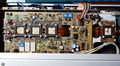
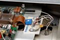
Power Supply
The 7104 uses a switch-mode power supply.
Module A23 (schematic page <14>) contains the mains rectifier, base drive circuitry, and power transistors of the inverter (aka, switcher). These transistors produce a 25 kHz waveform that is fed to the primary of T1310 (120-1183-00), whose secondaries provide the power for the rest of the scope.
Module A24 (also on schematic page <14>) contains the inverter control circuit and rectifiers for the secondaries of T1310. The inverter control circuit uses the 155-0067-02 inverter control IC, which is U1275.
Module A25 (schematic page <15>) contains the low-voltage regulators. There are independently regulated and current-limited sections for the −50 V, −15 V, +5 V, +15 V and +50 V rails. Each section has an opamp and a BJT output transistor in emitter-follower configuration.
The opamps need power, too. To avoid a dependency cycle, the power supplies for the opamps are separate low-current, low-efficiency zener clamps that in no way depend on the −50 V, −15 V, +5 V, +15 V or +50 V regulators. The power supplies for the opamps produce −22 V, −5.6 V, +5.6 V, and +22 V. To avoid exceeding the opamps' limit of 30 V total rail voltage, each opamp either gets −22 V and +5.6 V, or −5.6 V and +22 V, depending on whether it needs more output swing in the positive or negative direction.
The +50 V section produces the reference voltage ("50VS") for the other sections. It uses a 9 V zener diode, VR1412, as a reference.
The dependency relationship of the supplies is:
- The −50 V, −15 V, +5, and +15 V sections depend on
- the +50 V supply for reference voltage,
- the opamp supplies for to power their opamps, and
- the A24 semi-regulated rectifier outputs
- The +50 V depends on
- the opamp supplies (+22 V and −5.6 V) for to power its opamp,
- the A24 semi-regulated rectifier outputs (−54 and +54 V)
- The opamps supplies depend on
- the A24 semi-regulated rectifier outputs
- The semi-regulated rectifier outputs depend only on mains power to enter tick/burst mode. However, to enter normal mode, a variety of things need to be working properly.
Prices
| Year | 1980 | 1984 | 1990 | |
|---|---|---|---|---|
| Mainframe only | Catalog price | $14,400 | $21,380 | $29,995 |
| In 2023 Dollars | $53,700 | $63,200 | $70,500 | |
| Mainframe with 7A29, 7A29 Opt. 04, 7B15, 7B10 |
Catalog price | $21,730 | $31,875 | $44,510 |
| In 2023 Dollars | $81,000 | $94,200 | $104,600 |
Links
- Hans Springer's 1979 Electronic Design article on the 7104
- Reading Jim Williams: Scope Sunday 4
- Tek 7104 @ amplifier.cd
- Tek 7104 @ barrytech.com
- A Tektronix oscilloscope that moved faster than light? The Oregonian, 23 Sep 2011. (Original no longer accessible, link via archive.org.)
- Tektronix 7104 @ radiomuseum.org
Documents Referencing 7104
| Document | Class | Title | Authors | Year | Links |
|---|---|---|---|---|---|
| Tekscope 1979 V11 N1.pdf | Article | 1 GHz at 1 mV in a General Purpose Plug-in Oscilloscope | Hans Springer | 1979 | 7104 • Hypcon • SHFIII • 7A29 • 7B10 • 7B15 |
Pictures
-
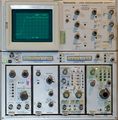
7104 front view (operating)
-
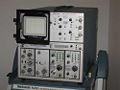
7104 with camera mounting frame on cart
-
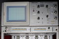
Front with empty plug-in bays
-
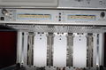
Plug-in bays
-
Rear view of 7104
-
Rear view of 7104
-
Probe power outlets
-
CRT label
-

CRT label
-
CRT Circuit
-
CRT Circuit
-
Front outputs
-

Readout board
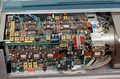
-

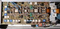
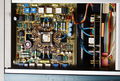
Interior right side
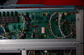
-
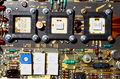
7104 horizontal (top) and vertical (bottom) output amplifiers
-
Vertical amplifier
-
Vertical amplifier close-up
-

Vertical amplifier, final stage close-up
-
Vertical CRT interconnect
-
Horizontal amplifier
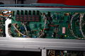
-
7104 horizontal output amplifier, CRT connection and termination of distributed horizontal deflection plates
-
Rear right (vertical channel switch board and mainframe interconnect)
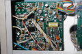
-
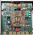
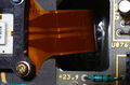
7104 vertical channel switch board
-
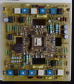
7104 vertical channel switch board
-
The upper half of the 7104 can be tilted upward for service. A metal support is included, like on the hood of a car.


Measurements
-
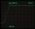
Rise time measurement. 150 ps risetime pulse from 067-0587-02 at 100 Hz repetition rate. Measured 240 ps (corrected for 150 ps fixture rise time: 190 ps = 1.8 GHz)
-
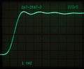
Rise time measurement as before, 1000 Hz repetition rate at same brightness settings.
-
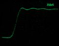
7104 recording a single shot pulse (from 067-0587-02) at 200 ps/Div. Camera: Nikon D7000, 50 mm f/1.4, ISO 3200, 1/2 s. CRT filter not removed.
-
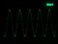
7104 recording 1 GHz sine, single sweep at 500 ps/Div. Camera: Nikon D7000, 50 mm f/1.4, ISO 3200, 1/2 s manually released. CRT filter not removed. CRT amplification loss is evident around the center line.
-
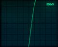
Faster-than-light beam on 7104? Using a 067-0587-02 calibration fixture at maximum amplitude produces this trace spanning 1.2 Div horizontally at 200 ps/Div and 8 Div vertically. Trace length is (1.2² + 8²)½ × 8.5 mm = 68.8 mm, travelled in 1.2 × 200 ps = 240 ps. Apparent speed is therefore 68.8×10⁻³ / 240×10-12 m/s or 2.86×10⁸ m/s. 95.6% c0 - a very near miss ...


Components
Some Parts Used in the 7104
| Part | Part Number(s) | Class | Description | Used in |
|---|---|---|---|---|
| 120-1183-00 | 120-1183-00 | Discrete component | power transformer | 7104 |
| 155-0009-00 | 155-0009-00 | Monolithic integrated circuit | horizontal lockout logic | 7504 • 7514 • 7704 • 7704A • R7704 • 7834 • 7844 • 7854 • 7904 • R7903 • 7904A • 7934 • 7104 |
| 155-0010-00 | 155-0010-00 | Monolithic integrated circuit | chop divider and blanking | 7504 • 7514 • 7704 • R7704 • 7704A • 7834 • 7854 • 7904 • R7903 • 7904A • 7934 • 7104 |
| 155-0011-00 | 155-0011-00 | Monolithic integrated circuit | clock and chop blanking | 485 • 7313 • 7403N • R7403N • 7503 • 7504 • 7514 • 7603 • AN/USM-281C • 7613 • 7623 • 7623A • 7633 • 7704 • R7704 • 7704A • 7834 • 7844 • 7854 • 7904 • 7904A • R7903 • R7912 • 7912AD • 7912HB • 7934 • 7104 • R7103 • AN/USM-281C |
| 155-0012-00 | 155-0012-00 | Monolithic integrated circuit | Z Axis Logic | 485 • 7504 • 7514 • 7704 • R7704 • 7704A • 7834 • 7844 • 7854 • 7904 • R7903 • 7904A • R7912 • 7934 • 7912AD • 7912HB • 7104 • R7103 |
| 155-0013-00 | 155-0013-00 • 155-0013-01 | Monolithic integrated circuit | horizontal chop and alt. binary | 7504 • 7514 • 7704 • R7704 • 7704A • 7834 • 7854 • 7904 • 7904A • R7903 • 7934 • 7104 |
| 155-0067-02 | 155-0067-00 • 155-0067-02 • 155-0067-03 | Monolithic integrated circuit | SMPS controller | 7704A • 7834 • 7844 • 7854 • 7904 • R7903 • 7904 • 7904A • 7934 • R7912 • 7912AD • 7912HB • 7934 • 7104 • R7103 • 308 • 434 • 485 • 690 • P7001 |
| 155-0078-00 | 155-0078-xx • 155-0273-00 • 155-0274-00 | Monolithic integrated circuit | broadband amplifier | 464 • 465 • 466 • 468 • 475 • 475A • 475M • 485 • 7834 • 7844 • 7854 • 7904 • R7903 • R7912 • 7912AD • 7912HB • 7104 • 7A16A • 7A16P • 7A24 • 7A26 • 7A42 • 067-0587-01 • 067-0680-00 • AM503 • PG502 • PG508 • DC510 • DC5010 • FG5010 |
| 155-0150-00 | 155-0150-00 | Hybrid integrated circuit | trigger detector | 7904A • 7104 • 7B10 • 7B15 • 7B92A • SCD1000 |
| 155-0173-00 | 155-0173-00 • 155-0173-05 | Hybrid integrated circuit | vertical channel switch | 7104 • R7103 • 7904A • 7934 • EG&G N-AM-173A |
| 155-0174-00 | 155-0174-00 | Monolithic integrated circuit | delay line compensator | 7104 • SCD1000 |
| 155-0175-00 | 155-0175-00 • 155-0175-05 | Monolithic integrated circuit | broadband amplifier | 7904A • 7912HB • 7934 • 7104 • R7103 • 7A29 • 7A29P • 7F10 • 067-0587-02 • 067-0587-10 • 11A71 • SCD1000 • EG&G N-AM-173A |
| 155-0176-00 | 155-0176-00 | Hybrid integrated circuit | vertical output amplifier | 7104 • SCD1000 |
| 155-0178-00 | 155-0178-00 • 155-0178-05 | Hybrid integrated circuit | horizontal output amplifier | 7904A • 7912HB • 7934 • 7104 |
| 155-0179-00 | 155-0179-00 | Hybrid integrated circuit | clamp circuit | 7104 |
| CA3046 | 156-0048-00 | Monolithic integrated circuit | transistor array | 7104 • 7403N • 7503 • 7B53A • 7D12 • DM502 • FG504 • S-52 • Telequipment D34 • 7603 • 7613 • 7623 • 7633 |
| T7100 | 154-0783-00 | CRT | micro-channel plate CRT | 7104 • R7103 |
| T7101 | CRT | micro-channel plate CRT | 7104 • R7103 |