7A13: Difference between revisions
(→Links) |
No edit summary |
||
| (28 intermediate revisions by 5 users not shown) | |||
| Line 1: | Line 1: | ||
{{Plugin Sidebar | {{Plugin Sidebar | ||
|manufacturer=Tektronix | |||
summary=100 MHz Differential Comparator | | |type=7A13 | ||
image=Tek 7a13 front.jpg | | |summary=100 MHz Differential Comparator | ||
caption=7A13 front panel (older version with mechanical voltage display) | | |image=Tek 7a13 front.jpg | ||
introduced=1969 | | |caption=7A13 front panel (older version with mechanical voltage display) | ||
discontinued=1992 | | |introduced=1969 | ||
series= | |discontinued=1992 | ||
manuals= | |series=7000-series scopes | ||
* [ | |designers=Bill DeVey | ||
* [ | |manuals= | ||
* [ | * [[Media:070-0978-00.pdf|Tektronix 7A13 Manual (sn < B200000)]] (OCR, color, split schematics) | ||
* [[Media:Tek-7a13 early.pdf|Tektronix 7A13 Manual (sn < B200000)]] (OCR, grayscale, whole schematics) | |||
* [[Media:070-1948-00.pdf|Tektronix 7A13 Instruction Manual (SN B200000-up)]] (OCR) | |||
* [[Media:070-1113-00.pdf|Tektronix 7A13 Instruction Manual (SN B0400000-up)]] | |||
* [[Media:TB-9-6625-2132-35.pdf|TB 9-6625-2132-35 Calibration Procedure for AM-6881/U (7A13) and AM-6786/U (7A22)]] (PDF, 2M) | |||
}} | }} | ||
The '''Tektronix 7A13''' is a "differential comparator" vertical plug-in for [[7000-series scopes]], i.e. a fast differential amplifier with adjustable DC offset. | |||
It is one of the first 7000 series plugins. | |||
It was designed by [[Bill DeVey]] and released along with the [[Introduction to the 7000-Series|first 7000-series scopes]] in 1969/1970, and was made until the 7000 series was retired in 1992. | |||
The | The 7A13 was known internally as the XA3 until just before release when the final nomenclature was determined. | ||
==Operation== | ==Operation== | ||
Older versions display the comparison (offset) voltage through a mechanical dial | Older versions display the comparison (offset) voltage through a mechanical dial. | ||
Newer versions (from 1976 on) display the comparison voltage on an LED panel meter. | |||
In addition, this voltage is brought out through a front panel connector so it can be measured externally. | In addition, this voltage is brought out through a front panel connector so it can be measured externally. | ||
In differential mode, a | In differential mode, a ±10 V common mode signal can be present at the inputs without attenuation. | ||
Either input can be switched to the comparison voltage, | Either input can be switched to the comparison voltage, which is settable to four digits by a 10-step switch and a 10-turn potentiometer. | ||
which is settable to four digits by a 10-step switch and a 10-turn potentiometer. | |||
In this comparator mode, the offset range is effectively 10,000 divisions. | In this comparator mode, the offset range is effectively 10,000 divisions. | ||
On the 1 mV/Div to 50 mV/Div ranges, the gate resistors can be disabled by an internal switch, | On the 1 mV/Div to 50 mV/Div ranges, the gate resistors can be disabled by an internal switch, raising DC input impedance to "approximately infinite" (as indicated by a front panel lamp). | ||
raising DC input impedance to "approximately infinite" (as indicated by a front panel lamp). | |||
{{BeginSpecs}} | {{BeginSpecs}} | ||
{{Spec | Bandwidth | 100 MHz (in 7700 or faster mainframes) }} | {{Spec | Bandwidth | 100 MHz (in 7700 or faster mainframes) }} | ||
{{Spec | | {{Spec | Risetime | 3.5 ns }} | ||
{{Spec | Deflection | {{Spec | Deflection | 1 mV/Div – 5 V/Div (1–2–5 sequence) }} | ||
{{Spec | Common | {{Spec | Common-mode range | at least ±10 V from 1 mV/Div to 5 mV/Div, ±100 V from 10 mV/Div to 50 mV/Div, ±500 V from 100 mV/Div to 5 V/Div }} | ||
{{Spec | Overdrive | {{Spec | Overdrive recovery | to within 2 mV in 1µs (at 1 mV/Div) }} | ||
{{Spec | CMRR | | {{Spec | CMRR | ≥10,000:1 for 10 V<sub>p-p</sub> or less, 100 kHz to 1 MHz, decreasing to 500:1 at 10 MHz with 1 V<sub>p-p</sub>, 200:1 at 20 MHz with 1 V<sub>p-p</sub> }} | ||
{{Spec | Input impedance | 1 MΩ // 20 pF }} | {{Spec | Input impedance | 1 MΩ // 20 pF }} | ||
{{Spec | Comparison voltage | | {{Spec | Comparison voltage | −10 V to +10 V }} | ||
{{Spec | | {{Spec | V<sub>c</sub> reading accuracy | | ||
Mechanical version: 0.1% of reading + 5 mV | Mechanical version: 0.1% of reading + 5 mV | ||
<br />DVM version: 0.1% of reading + 3 mV}} | <br />DVM version: 0.1% of reading + 3 mV}} | ||
{{Spec | Warmup time | 5 minutes for short-term measurements, 1 hour for best stability }} | {{Spec | Warmup time | 5 minutes for short-term measurements, 1 hour for best stability }} | ||
{{EndSpecs}} | {{EndSpecs}} | ||
==Links== | |||
{{Documents|Link=7A13}} | |||
==Power Consumption== | ==Power Consumption== | ||
The power consumption of a 7A13 was measured to be: | The power consumption of a 7A13 was measured to be: | ||
* + | * +50 V: 75 mA | ||
* | * −50 V: 66 mA | ||
* + | * +15 V: 238 mA | ||
* | * −15 V: 204 mA | ||
* + | * +5 V (logic): 279 mA | ||
* + | * +5 V (lights): 228 mA | ||
==Internals== | ==Internals== | ||
In the older version, the comparison voltage is generated from a precision zener supplied from either positive or negative 50 V rail, followed by a 10-step switched divider made of 0.1% resistors to select the first digit. | In the older version, the comparison voltage is generated from a precision zener supplied from either positive or negative 50 V rail, | ||
followed by a 10-step switched divider made of 0.1% resistors to select the first digit. | |||
For the lower three digits, a ten-turn potentiometer with a mechanical digital readout is used. | |||
The V/Div switch changes the decimal point on the readout, | |||
which is implemented through small light bulbs above the dial with plastic light guides to make the decimal point appear between the digits. | |||
In contrast to the [[back-lit switches]], the decimal point lamps are supplied from logic +5 V | |||
so they work also in mainframes without switch light supplies, e.g. the 76x3s. | |||
In the newer version, the zener-derived reference voltage is always positive. | In the newer version, the zener-derived reference voltage is always positive. | ||
A 10-turn pot for coarse selection combines with a single-turn pot for fine control. | |||
The resultant voltage is displayed on a 4-digit simplified DVM built around a [[Fairchild 3814]] 4½ digit DVM controller. | |||
For negative values of V<sub>C</sub>, an opamp polarity inverter circuit is switched in. | |||
The 7A13 uses the ±50 V supplies provided by the mainframe. | |||
===Repair issues=== | ===Repair issues=== | ||
The 7A13 uses twelve miniature relays similar to those used in the [[7A11]]. These are very rare. | The 7A13 uses twelve [[miniature relays]] similar to those used in the [[7A11]]. These are very rare. | ||
The [http://www.amplifier.cd/Test_Equipment/Tektronix/Tektronix_7000_series_amplifier/amplifier_7A11.htm 7A11 repair report at amplifier.cd] | |||
describes a possible replacement with a modern component. See also the IK1ZYW link below. | |||
Early 7A13 plug-ins were made with a mechanical counter for reading out the comparison voltage. | Early 7A13 plug-ins were made with a mechanical counter for reading out the comparison voltage. | ||
The plastic gears in this counter don't age well. | The plastic gears in this counter don't age well. | ||
The plug-in can still be used when the counter fails, by using an | The plug-in can still be used when the counter fails, by using an | ||
external voltmeter to monitor the comparison voltage, | external voltmeter to monitor the comparison voltage, V<sub>c</sub>. | ||
Later 7A13 plug-ins use an LED readout instead of the mechanical counter. | Later 7A13 plug-ins use an LED readout instead of the mechanical counter. | ||
The LED readout is much less problematic. | The LED readout is much less problematic. | ||
| Line 75: | Line 90: | ||
==Links== | ==Links== | ||
* [[Media:Tekscope 1970 V2 N5 Oct 1970.pdf | * [[Media:Tekscope 1970 V2 N5 Oct 1970.pdf|Amplitude measurements to better than 1%. Tekscope Vol. 2 No. 5, October 1970]] | ||
* [http://www.amplifier.cd/Test_Equipment/Tektronix/Tektronix_7000_series_amplifier/amplifier_7A13.htm Tek 7A13 @ amplifier.cd] | * [http://www.amplifier.cd/Test_Equipment/Tektronix/Tektronix_7000_series_amplifier/amplifier_7A13.htm Tek 7A13 @ amplifier.cd] | ||
* [http://www.barrytech.com/tektronix/tek7000/tek7a13.html Tek 7A13 @ barrytech.com] | * [http://www.barrytech.com/tektronix/tek7000/tek7a13.html Tek 7A13 @ barrytech.com] | ||
* [http://www.radiomuseum.org/r/tektronix_differential_comparator_unit_7a13.html Tek 7A13 @ radiomuseum.org] | * [http://www.radiomuseum.org/r/tektronix_differential_comparator_unit_7a13.html Tek 7A13 @ radiomuseum.org] | ||
* [http://ik1zyw.blogspot. | * [http://ik1zyw.blogspot.com/2007/09/tektronix-7a13-broken-relays.html Tek 7A13 broken relays @ IK1ZYW Labs] | ||
* [http://www.pa4tim.nl/?p=5755 Repairing 7A13 relays @ PA4TIM] (how to take relays apart, inside photos) | * [http://www.pa4tim.nl/?p=5755 Repairing 7A13 relays @ PA4TIM] (how to take relays apart, inside photos) | ||
* [https://www.youtube.com/watch?v=IqE_LNXnPyo Tektronix 7A13 Repair and Alignment] by Zenwizard Studios @ YouTube | |||
==Pictures== | ==Pictures== | ||
| Line 87: | Line 103: | ||
<gallery> | <gallery> | ||
Tek 7a13 front.jpg | 7A13 older version, front view | |||
Tek-7a13-left.jpg | 7A13, left side | |||
Tek-7a13-right.jpg | 7A13, right side | |||
7a13-dials1.jpg | closeup of mechanical V<sub>C</sub> display in operation | |||
7a13-dials2.jpg | Three light bulbs above the digit dials for decimal point indication | |||
7a13-gears1.jpg | Gear mechanism | |||
7a13-gears2.jpg | Gear mechanism. If the leftmost display digit is misaligned with respect to the switch position, the left pair of bevel gears seen here need to be rotated relatively to each other. | |||
</gallery> | </gallery> | ||
| Line 99: | Line 115: | ||
<gallery> | <gallery> | ||
7a13a-front.jpg | 7A13 newer version, front view | |||
7a13a-left.jpg | 7A13 newer version, left interior | |||
7a13a-right.jpg | 7A13 newer version, right interior (some non-original relays) | |||
Tek 7a13 late 1.jpg|Later version of 7A13 | |||
Tek 7a13 late 2.jpg|Later version of 7A13 | |||
Tek 7a13 late 3.jpg|Later version of 7A13 | |||
Tek 7a13 late 4.jpg|Later version of 7A13 | |||
Tek 7a13 late 5.jpg|Later version of 7A13 | |||
Tek 7a13 late 6.jpg|Later version of 7A13 | |||
Tek 7a13 late 7.jpg|Later version of 7A13 | |||
Tek 7a13 2345.jpg | |||
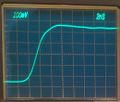
Tek 7a13 step response.jpg|Step response of 7A13 using [[S-52]] and [[7704A]]. Overall rise time is 3.3 ns. | |||
</gallery> | </gallery> | ||
==Components== | |||
{{Parts|7A13}} | |||
[[Category:7000 series vertical plugins]] | [[Category:7000 series vertical plugins]] | ||
[[Category:Differential amplifiers]] | |||
Latest revision as of 09:02, 7 December 2023

The Tektronix 7A13 is a "differential comparator" vertical plug-in for 7000-series scopes, i.e. a fast differential amplifier with adjustable DC offset. It is one of the first 7000 series plugins. It was designed by Bill DeVey and released along with the first 7000-series scopes in 1969/1970, and was made until the 7000 series was retired in 1992.
The 7A13 was known internally as the XA3 until just before release when the final nomenclature was determined.
Operation
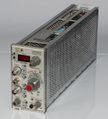
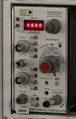
Older versions display the comparison (offset) voltage through a mechanical dial. Newer versions (from 1976 on) display the comparison voltage on an LED panel meter. In addition, this voltage is brought out through a front panel connector so it can be measured externally.
In differential mode, a ±10 V common mode signal can be present at the inputs without attenuation. Either input can be switched to the comparison voltage, which is settable to four digits by a 10-step switch and a 10-turn potentiometer. In this comparator mode, the offset range is effectively 10,000 divisions.
On the 1 mV/Div to 50 mV/Div ranges, the gate resistors can be disabled by an internal switch, raising DC input impedance to "approximately infinite" (as indicated by a front panel lamp).
Key Specifications
| Bandwidth | 100 MHz (in 7700 or faster mainframes) |
|---|---|
| Risetime | 3.5 ns |
| Deflection | 1 mV/Div – 5 V/Div (1–2–5 sequence) |
| Common-mode range | at least ±10 V from 1 mV/Div to 5 mV/Div, ±100 V from 10 mV/Div to 50 mV/Div, ±500 V from 100 mV/Div to 5 V/Div |
| Overdrive recovery | to within 2 mV in 1µs (at 1 mV/Div) |
| CMRR | ≥10,000:1 for 10 Vp-p or less, 100 kHz to 1 MHz, decreasing to 500:1 at 10 MHz with 1 Vp-p, 200:1 at 20 MHz with 1 Vp-p |
| Input impedance | 1 MΩ // 20 pF |
| Comparison voltage | −10 V to +10 V |
| Vc reading accuracy |
Mechanical version: 0.1% of reading + 5 mV
|
| Warmup time | 5 minutes for short-term measurements, 1 hour for best stability |
Links
Documents Referencing 7A13
| Document | Class | Title | Authors | Year | Links |
|---|---|---|---|---|---|
| Tekscope 1969 V1 N5 Oct 1969.pdf | Article | Introducing the New Generation | 1969 | 7000-series scopes • 7504 • 7704 • 7A11 • 7A12 • 7A13 • 7A14 • 7A16 • 7A22 • 7S11 • 7M11 • 7B50 • 7B51 • 7B70 • 7B71 • 7T11 • R5030 • 7000 series readout system • Miniature relays • Cam switches • Industrial Design • T7500 • T7700 • P6052 • P6053 • C-50 • C-51 • 204-2 | |
| Tekscope 1969 V1 N6 Dec 1969.pdf | Article | A New Logic for Oscilloscope Displays | 1969 | 7000-series scopes • 7A11 • 7A12 • 7A13 • 7A14 • 7A16 • 7A22 • 7B50 • 7B51 • 7B70 • 7B71 • 7S11 • 7T11 • 7504 • 7704 | |
| Tekscope 1970 V2 N5 Oct 1970.pdf | Article | Amplitude Measurement to Better Than 1% | 1970 | 1S1 • 7503 • 7A13 • 1A5 • W • 3A7 | |
| Tekscope 1972 V4 N5 Sep 1972.pdf | Article | A Practical Approach to Differential Amplifiers and Measurements | Fred Beckett | 1972 | 112 • 11A33 • 1A5 • 1A6 • 1A7 • 1A7A • 26A2 • 3A9 • 5A22N • 7A13 • 7A22 • AM502 • D • E • G • P6055 • P6046 • W • Z |
| Tekscope 1972 V4 N6 Nov 1972.pdf | Article | Differential Amplifiers and Measurements, Part 2 | Fred Beckett | 1972 | 112 • 11A33 • 1A5 • 1A6 • 1A7 • 1A7A • 26A2 • 3A9 • 5A22N • 7A13 • 7A22 • AM502 • D • E • G • P6055 • P6046 • W • Z |
Power Consumption
The power consumption of a 7A13 was measured to be:
- +50 V: 75 mA
- −50 V: 66 mA
- +15 V: 238 mA
- −15 V: 204 mA
- +5 V (logic): 279 mA
- +5 V (lights): 228 mA
Internals
In the older version, the comparison voltage is generated from a precision zener supplied from either positive or negative 50 V rail, followed by a 10-step switched divider made of 0.1% resistors to select the first digit. For the lower three digits, a ten-turn potentiometer with a mechanical digital readout is used. The V/Div switch changes the decimal point on the readout, which is implemented through small light bulbs above the dial with plastic light guides to make the decimal point appear between the digits. In contrast to the back-lit switches, the decimal point lamps are supplied from logic +5 V so they work also in mainframes without switch light supplies, e.g. the 76x3s.
In the newer version, the zener-derived reference voltage is always positive. A 10-turn pot for coarse selection combines with a single-turn pot for fine control. The resultant voltage is displayed on a 4-digit simplified DVM built around a Fairchild 3814 4½ digit DVM controller. For negative values of VC, an opamp polarity inverter circuit is switched in.
The 7A13 uses the ±50 V supplies provided by the mainframe.
Repair issues
The 7A13 uses twelve miniature relays similar to those used in the 7A11. These are very rare. The 7A11 repair report at amplifier.cd describes a possible replacement with a modern component. See also the IK1ZYW link below.
Early 7A13 plug-ins were made with a mechanical counter for reading out the comparison voltage. The plastic gears in this counter don't age well. The plug-in can still be used when the counter fails, by using an external voltmeter to monitor the comparison voltage, Vc.
Later 7A13 plug-ins use an LED readout instead of the mechanical counter. The LED readout is much less problematic.
Links
- Amplitude measurements to better than 1%. Tekscope Vol. 2 No. 5, October 1970
- Tek 7A13 @ amplifier.cd
- Tek 7A13 @ barrytech.com
- Tek 7A13 @ radiomuseum.org
- Tek 7A13 broken relays @ IK1ZYW Labs
- Repairing 7A13 relays @ PA4TIM (how to take relays apart, inside photos)
- Tektronix 7A13 Repair and Alignment by Zenwizard Studios @ YouTube
Pictures
Older version (1970-1975, mechanical meter)
-
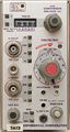
7A13 older version, front view
-
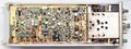
7A13, left side
-
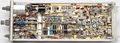
7A13, right side
-
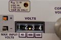
closeup of mechanical VC display in operation
-
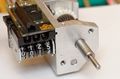
Three light bulbs above the digit dials for decimal point indication
-
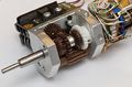
Gear mechanism
-
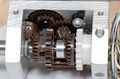
Gear mechanism. If the leftmost display digit is misaligned with respect to the switch position, the left pair of bevel gears seen here need to be rotated relatively to each other.


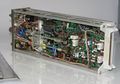
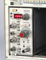
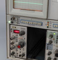
Newer version (1976-1992, LED meter)
-
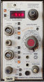
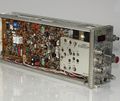
7A13 newer version, front view
-
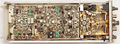
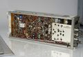
7A13 newer version, left interior
-
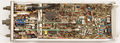
7A13 newer version, right interior (some non-original relays)
-
Later version of 7A13
-
Later version of 7A13
-
Later version of 7A13
-
Later version of 7A13
-
Later version of 7A13
-
Later version of 7A13
-
Later version of 7A13
-

-


Components
Some Parts Used in the 7A13
| Part | Part Number(s) | Class | Description | Used in |
|---|---|---|---|---|
| 148-0034-00 | 148-0034-00 | Discrete component | miniature DPDT relay | 7A11 • 7A13 • 7A14 • 7B70 • 7B71 • 7503 • 7904 • 7904A |
| 148-0035-00 | 148-0035-00 | Discrete component | miniature SPDT relay | 7A13 • 7A14 • 7B70 • 7B71 |
| 148-0050-00 | 148-0050-00 | Discrete component | miniature SPDT relay | 7A13 |
| 148-0054-00 | 148-0054-00 | Discrete component | miniature SPDT+SPST relay | 7A13 |
| 148-0055-00 | 148-0055-00 | Discrete component | miniature SPDT+SPST relay | 7A13 |
| Fairchild 3814 | 156-0306-00 | Monolithic integrated circuit | 4½ digit dual-slope DVM controller | 7A13 • 7L13 • 7L18 • DM501 |