S-4: Difference between revisions
mNo edit summary |
No edit summary |
||
| (19 intermediate revisions by 3 users not shown) | |||
| Line 1: | Line 1: | ||
{{Plugin Sidebar 2 | | |||
title=Tektronix S-4 | | |||
summary=Sampling Head | | |||
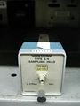
image=Tek-s-4.jpg | | |||
caption=S-4 head | | |||
series={{3S+7S}} | | |||
introduced=1968 | | |||
discontinued=1990 | | |||
manuals= | |||
* [http://w140.com/tek_s4.pdf Tektronix S-4 Manual, copyright 1969 (PDF)] | |||
* [http://w140.com/tek_S4_1985.pdf Tektronix S-4 Manual, revised 1985 (PDF)] | |||
* [http://w140.com/frye_s4_gate.pdf George Frye's Explanation of S-4 sampler in October 1968 Service Scope (PDF)] | |||
}} | |||
The '''Tektronix S-4''' is a sampling head for 7000- and 3S-series samplers. It was designed by [[George Frye]] and [[introduced in 1968]]. It is the fastest of the S-series plug-in samplers. | |||
The | {{BeginSpecs}} | ||
{{Spec | Rise time | 25 ps (observed with [[S-50]] or [[S-52]], 35 ps) }} | |||
{{Spec | Bandwidth | 14.5 GHz }} | |||
{{Spec | Input impedance | 50 Ω (terminated [[SMA connector]])}} | |||
{{Spec | Input range | operating, 1 V<sub>p-p</sub>; max. safe overload, ±5 V }} | |||
{{Spec | Noise | < 5 mV}} | |||
{{Spec | Features | | |||
* trigger signal pick-off for internal triggering | |||
}} | |||
{{EndSpecs}} | |||
==Internals== | |||
The S-4 sampling gate is based upon a traveling wave trapped-charge transmission line in which the sampling window is set by the propagation time of a pulse edge through a thick-film transmission line. This technique requires only a sharp pulse edge rather than a precise pulse width, which is harder to generate. | |||
The sampling diodes are housed in a special coaxial connector that provides a high bandwidth signal path. | The sampling diodes are housed in a special coaxial connector that provides a high bandwidth signal path. | ||
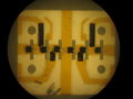
To disassemble the sampler hybrid, first remove it from the sampler board as per the manual. Remove the input | |||
connector using a 7/32" wrench and remove the 20 dB attenuator with small plyers. The ceramic board is held | |||
to the housing using roll pins that can be pressed out with a 0.030" pin punch. The hybrid has six diodes, | |||
each about 0.75mm square. The cathodes are glued to the gold substrate with conductive epoxy and the anodes | |||
are wire-bonded (twice) over a gap to the next step in the strobe line. It appears that a standard beam-lead | |||
diode may fit across the gap but cleanly removing a failed diode without damaging the substrate would be | |||
quite difficult. | |||
==Links== | |||
* [http://www.amplifier.cd/Test_Equipment/Tektronix/Tektronix_7000_series_special/S4.html S-4 page @ amplifier.cd] | |||
* [https://kh6htv.files.wordpress.com/2015/11/an-02a-oscopes.pdf James R. Andrews, ''Comparison of Ultra-Fast Rise Sampling Oscilloscopes''. Picosecond Pulse Labs App Note AN-2a, 1989] | |||
==Pictures== | |||
<gallery> | <gallery> | ||
File:Tek-s-4.jpg | |||
File:Tek s4.jpg | |||
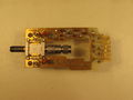
File:S4_top.jpg|Top view of the S4 plug-in | |||
File:S4_left.jpg|Left view | |||
File:S4_right.jpg|Right view | |||
File:S4 schem.png|Schematic | |||
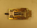
File:Tektronix-S4-sampler-board-strobe.jpg|Sampler board, strobe side | |||
File:Tektronix-S4-sampler-board-preamp.jpg|Sampler board, preamp side | |||
File:Tektronix-S4-sampler-board-hybrid.jpg|Sampler board, disassembled with parts orientation | |||
File:Tektronix-S4-hybrid-internal.jpg|Microphotograph of sampler hybrid | |||
</gallery> | </gallery> | ||
[[Category:7000 and 3S series sampling heads]] | |||
Revision as of 08:14, 23 February 2017
Template:Plugin Sidebar 2 The Tektronix S-4 is a sampling head for 7000- and 3S-series samplers. It was designed by George Frye and introduced in 1968. It is the fastest of the S-series plug-in samplers.
Key Specifications
| Rise time | 25 ps (observed with S-50 or S-52, 35 ps) |
|---|---|
| Bandwidth | 14.5 GHz |
| Input impedance | 50 Ω (terminated SMA connector) |
| Input range | operating, 1 Vp-p; max. safe overload, ±5 V |
| Noise | < 5 mV |
| Features |
|
Internals
The S-4 sampling gate is based upon a traveling wave trapped-charge transmission line in which the sampling window is set by the propagation time of a pulse edge through a thick-film transmission line. This technique requires only a sharp pulse edge rather than a precise pulse width, which is harder to generate. The sampling diodes are housed in a special coaxial connector that provides a high bandwidth signal path.
To disassemble the sampler hybrid, first remove it from the sampler board as per the manual. Remove the input connector using a 7/32" wrench and remove the 20 dB attenuator with small plyers. The ceramic board is held to the housing using roll pins that can be pressed out with a 0.030" pin punch. The hybrid has six diodes, each about 0.75mm square. The cathodes are glued to the gold substrate with conductive epoxy and the anodes are wire-bonded (twice) over a gap to the next step in the strobe line. It appears that a standard beam-lead diode may fit across the gap but cleanly removing a failed diode without damaging the substrate would be quite difficult.
Links
- S-4 page @ amplifier.cd
- James R. Andrews, Comparison of Ultra-Fast Rise Sampling Oscilloscopes. Picosecond Pulse Labs App Note AN-2a, 1989
Pictures
-

-
-
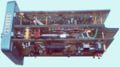
Top view of the S4 plug-in
-
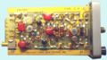
Left view
-
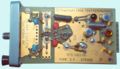
Right view
-
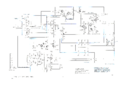
Schematic
-
Sampler board, strobe side
-
Sampler board, preamp side
-
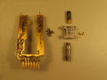
Sampler board, disassembled with parts orientation
-
Microphotograph of sampler hybrid


