P6202: Difference between revisions
No edit summary |
No edit summary |
||
| Line 19: | Line 19: | ||
{{Spec | Bandwidth | DC to 500 MHz (16 Hz lower limit with additional AC coupling tip) }} | {{Spec | Bandwidth | DC to 500 MHz (16 Hz lower limit with additional AC coupling tip) }} | ||
{{Spec | Rise time | < 0.7 ns }} | {{Spec | Rise time | < 0.7 ns }} | ||
{{Spec | Attenuation | 10 : 1 (100 : 1 with additional 10× attenuator tip) }} | {{Spec | Attenuation | 10 : 1 (100 : 1 with additional 10× attenuator tip, 010-0384-00) }} | ||
{{Spec | Input impedance | 10 MΩ // 2 pF with or without additional 10× attenuator tip, +2 pF for AC coupling tip }} | {{Spec | Input impedance | 10 MΩ // 2 pF with or without additional 10× attenuator tip, +2 pF for AC coupling tip }} | ||
{{Spec | Input range | ± 6 V (± 60 V with additional 10× attenuator tip) }} | {{Spec | Input range | ± 6 V (± 60 V with additional 10× attenuator tip) }} | ||
| Line 34: | Line 34: | ||
<gallery> | <gallery> | ||
Tek-p6202-case-open.jpg | Carrying case | Tek-p6202-case-open.jpg | Carrying case | ||
Tek-p6202-in-case.jpg | Probe in case, with power supply, 10:1 pre-divider tip, hook tip, AC coupling tip and connection box. | Tek-p6202-in-case.jpg | Probe in case, with power supply, 10:1 pre-divider tip (010-0384-00), hook tip, AC coupling tip and connection box. | ||
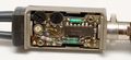
Tek-p6202-tip-1.jpg | Amplifier in probe tip (SMD components in 1976!) | Tek-p6202-tip-1.jpg | Amplifier in probe tip (SMD components in 1976!) | ||
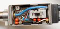
Tek-p6202-tip-2.jpg | Amplifier in probe tip, reverse | Tek-p6202-tip-2.jpg | Amplifier in probe tip, reverse | ||
Revision as of 04:55, 28 February 2018
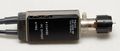
Template:Plugin Sidebar 2 The Tektronix P6202 is a 500 MHz active 10× FET probe with 50 Ω output impedance, introduced in 1976.
The 6202 has its own mains power supply, the 6202A (1980) has a LEMO S-series connector fitting the 7000-series scopes' probe power outlets.
Key Specifications
| Bandwidth | DC to 500 MHz (16 Hz lower limit with additional AC coupling tip) |
|---|---|
| Rise time | < 0.7 ns |
| Attenuation | 10 : 1 (100 : 1 with additional 10× attenuator tip, 010-0384-00) |
| Input impedance | 10 MΩ // 2 pF with or without additional 10× attenuator tip, +2 pF for AC coupling tip |
| Input range | ± 6 V (± 60 V with additional 10× attenuator tip) |
| DC Offset range | ± 55 V (± 200 V with additional 10× attenuator tip) |
| Max input | ± 200 V (nondestructive) |
| Signal cable length | 2 m (6.5') |
Internals
An initial 8 MΩ : 2 MΩ divider drives a dual JFET (source follower + current source), a PNP emitter follower and finally an NPN emitter follower as a cable driver. These stages use SMD components located in the probe tip. The probe control box at the end of the coax only contains a ±7 V regulator, a switchable 50 Ω terminator, and the offset potentiometers that supply ±15 V to the bottom of the input divider. There is no input protection apart from the divider.
Pictures
-
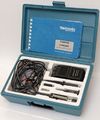
Carrying case
-
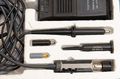
Probe in case, with power supply, 10:1 pre-divider tip (010-0384-00), hook tip, AC coupling tip and connection box.
-
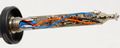
Amplifier in probe tip (SMD components in 1976!)
-
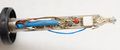
Amplifier in probe tip, reverse
-
Connection box
-
-

-
-
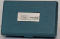
Case exterior
-
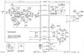
schematic


Measurements
Rise time of a P6202 500 MHz FET probe measured on a 7S12 plugin in a 7844 mainframe (with 25 ps S-52 pulse generator head and 25 ps S-4 sampling head). Measured rise time ~440 ps observed on this specimen is equivalent to 795 MHz bandwidth.
-

at 1 ns/Div
-
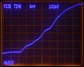
at 100 ps/Div

