P6451: Difference between revisions
No edit summary |
No edit summary |
||
| Line 20: | Line 20: | ||
==Manuals== | ==Manuals== | ||
* [[Media:062-2372-00.pdf| P6451 Data Sheet (062-2372-00)] (1976) | * [[Media:062-2372-00.pdf| P6451 Data Sheet (062-2372-00)]] (1976) | ||
* [[Media:070-2515-00.pdf|P6451 Instructions (070-2515-00)]] (1980) | * [[Media:070-2515-00.pdf|P6451 Instructions (070-2515-00)]] (1980) | ||
==Links== | ==Links== | ||
Revision as of 20:36, 10 May 2019

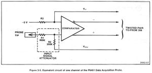
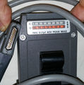
The Tektronix P6451 is an 8+1 channel active logic probe designed for use with the 7D01, 7D02, DL502, LA501A, WR501, 308, 318, and 338. It presents nine balanced signals back to the input section of the analyzer − 8 data channels, plus a 9th channel that is used either as a clock or as a qualifier.

The P6451 has the ability to set different threshold voltages for each of three channel groups − 1-4, 5-8, and the 9th (called 'C' in the manual).
The only active components are two 155-0137-00 custom hybrid pre-amp/comparator modules containing comparators with FET inputs and differential ECL outputs that can drive terminated 100 Ω lines. The instrument input would contain differential ECL receivers like the 10115 or 10216.
The P6451 uses the P64xx-family 10-wire input lead harnesses with 0.2"-spaced connectors. Is also possible to use standard jumper wires with pins, sockets or clips on the other end for connecting inputs.
Part numbers for the P6451 are 010-6451-03 (straight connector) or 010-6451-05 (90° connector e.g. for 308).
Key Specifications
| Maximum Voltage | ±40 V nondestructive |
|---|---|
| Input impedance | 1 MΩ // 5±1 pF (without input leads) |
| Delay time | 17±2 ns with ±1 V input and threshold at 0 V |
| Power | 5 V, 260 mA |


