502: Difference between revisions
No edit summary |
No edit summary |
||
| (34 intermediate revisions by 5 users not shown) | |||
| Line 2: | Line 2: | ||
title=Tektronix 502 | | title=Tektronix 502 | | ||
summary=1 MHz dual beam differential scope | | summary=1 MHz dual beam differential scope | | ||
image= | image=Tek 502 with x-y display.jpg | | ||
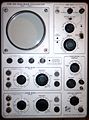
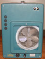
caption=Tek 502 front | | caption=Tek 502 front (with Single Sweep Mod 104)| | ||
introduced=1958 | | introduced=1958 | | ||
discontinued=1973 | | discontinued=1973 | | ||
manuals= | manuals= | ||
* [http://w140.com/tek_502.pdf Tektronix 502 Manual (PDF)] | * [[Media:IM-502-1.pdf|502 (early) Instruction]] (OCR PDF, 15M) | ||
* [ | * [[Media:070-090.pdf|502 (late) Instruction]] (OCR PDF, 26M) | ||
* [[Media:070-382.pdf|502A Instruction]] (OCR PDF, 8M) | |||
<!-- * [http://w140.com/tek_502.pdf Tektronix 502 Manual (PDF)] --> | |||
* [[Media:070-0382-02.pdf|502A/RM502A (late) Instruction)]] (PDF, 20M) | |||
* [[Media:Tek 502a fcp sn31k-up june 1969.pdf | Tektronix 502A sn 31,000-up Factory Calibration Procedure, June 1969 (PDF, needs OCR)]] | |||
* [[Media:Tek 502a cal outline.pdf]] | |||
}} | }} | ||
The '''Tektronix 502''' is a dual-beam oscilloscope [[introduced in 1958]], followed by the 502A in 1963. | The '''Tektronix 502''' is a dual-beam oscilloscope [[introduced in 1958]], followed by the 502A in 1963. | ||
There is also a rack-mount model, the RM502A. | |||
Both beams have differential inputs. | Both beams have differential inputs. The horizontal deflection plates are common to both beams. | ||
Mod 104 on a 502 provides single sweep lockout. This feature is standard on the 502A, which also has beam finder switches for each channel. | |||
A recessed switch in the left side panel allows the upper beam amplifier to be connected to the horizontal deflection plates for single-beam X-Y operation, providing a differential X input with the same sensitivity as the Y channel. The upper beam is positioned off screen in this mode. | |||
If the combination of time base setting and magnification selector results in a sweep faster than 1 μs/div, the horizontal scale is not calibrated, and a lamp on the front panel lights up to remind the operator of that. | |||
{{BeginSpecs}} | |||
{{Spec | Deflection | 100 μV/cm to 20 V/cm, 1−2−5, ±3% }} | |||
{{Spec | Bandwidth | 1 MHz @ 200 mV/cm and above; 400 kHz @ 50 mV/cm, 200 kHz @ 5 mV/cm, 100 kHz @ 200 μV/cm }} | |||
{{Spec | CMRR | 502A: 40,000:1 @ 100 mV/cm and 1 kHz }} | |||
{{Spec | Input impedance | 1 MΩ // 47 pF }} | |||
{{Spec | Sweep | 1 μs/cm to 5 s/cm, 1−2−5, ±3%; magnifier ×2, ×5, ×10 or ×20 }} | |||
{{Spec | CRT | Early 502: Type [[T60P2]]/[[T502P2]]/[[T5020P2]];<br />Late 502, 502A: Type [[T5021P2]];<br />(P1, P7 or P11 were available as options)<br />10 vertical and 10 horizontal 1 cm divisions<br />3 kV acceleration }} | |||
{{Spec | Dimensions | 597 mm (23½") × 286 mm (11¼") × 381 mm (15") L×W×H }} | |||
{{spec | Weight | 23.6 kg (52lb) }} | |||
{{EndSpecs}} | |||
==Prices== | ==Prices== | ||
{| class="wikitable" | {| class="wikitable" | ||
|- | |- | ||
| Line 50: | Line 62: | ||
==Internals== | ==Internals== | ||
The −150 V supply uses a [[5651]] voltage reference tube as its reference. | |||
The | |||
The 6.2 V<sub>DC</sub> heater supply for the tubes in the first stage differential amplifier is transistor-regulated. | |||
This heater supply uses the −150 V supply as its reference. | |||
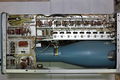
There is no post-deflection acceleration. The CRT cathode voltage is −2.9 kV. | |||
The 502 uses a single supply for the upper beam and lower beam CRT cathodes. | The early 502 uses a single supply for the upper beam and lower beam CRT cathodes (HV transformer [[120-114]]). | ||
Later models (1959+, see [[Media:070-090.pdf|070-090]]) and the 502A have separate supplies for the two CRT cathodes (HV transformer [[120-150]]). | |||
This improvement | This improvement allows slight differences in horizontal CRT sensitivity between | ||
to be | the two beams to be cancelled out in step 8 of the calibration procedure. | ||
Later 502A models have a solid state (plus [[nuvistor]]) input stage, | |||
a [[6DJ8]] as the deflection amplifier, and transistors as amplifiers and emitter followers (only in the newest version). | |||
The 502 has a 123 °F (50.5 °C) [[thermal cutoff]] switch. | |||
==Links== | ==Links== | ||
* [http://www.amplifier.cd/Test_Equipment/Tektronix/Tektronix_other/502A.htm Tektronix 502A] @ amplifier.cd (many internal pictures) | * [http://www.amplifier.cd/Test_Equipment/Tektronix/Tektronix_other/502A.htm Tektronix 502A] @ amplifier.cd (many internal pictures) | ||
* [https://youtu.be/0D-z6_M76Ls Tektronix 502A internals] @ youtube (German) | |||
==Pictures== | ==Pictures== | ||
===502=== | ===502=== | ||
<gallery> | <gallery> | ||
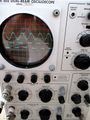
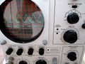
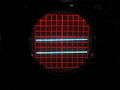
Tek 502 | Tek 502 with x-y display.jpg | 502 with (single-beam) X-Y display | ||
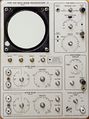
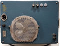
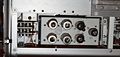
Tek_502_front.jpg | 502 Mod.104 (single sweep), front | |||
Tek_502_front.jpg|502 front | Tek 502 front fl.jpg | 502 Mod.104 (single sweep), front from lower left | ||
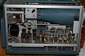
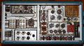
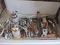
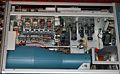
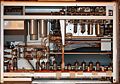
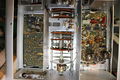
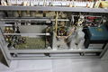
Tek 502 left.jpg | 502 left interior | |||
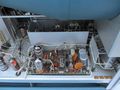
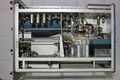
Tek 502 left.jpg|502 left | Tek 502 right.jpg | 502 right interior | ||
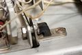
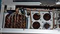
Tek 502 right.jpg|502 right | 502 amplifier shock mount.jpg | rubber shock mount of amplifier sub-chassis | ||
Tek 502 bottom.jpg|502 bottom | Tek 502 bottom.jpg | 502 bottom | ||
Tek 502 trace.jpg | 502 trace | |||
Tek 502 trace2.jpg | 502 trace | |||
Tek 502 front panel wo knobs.jpg | 502 front panel without knobs | |||
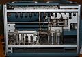
502 power supply operating.jpg | 502 power supply section in operation | |||
</gallery> | </gallery> | ||
| Line 105: | Line 122: | ||
</gallery> | </gallery> | ||
=== Third version 502A, serial number | === Third version 502A, serial number ≥31,000 === | ||
<gallery> | <gallery> | ||
Tek 502a last generation attenuator.jpg|top side lower beam input amp and attenuator, bottom side of upper beam vert input board | Tek 502a last generation attenuator.jpg|top side lower beam input amp and attenuator, bottom side of upper beam vert input board | ||
| Line 119: | Line 136: | ||
===Diagrams=== | ===Diagrams=== | ||
<gallery> | <gallery> | ||
Tek 502a block.png|502A block diagram | Tek 502a block.png | 502A block diagram | ||
Tek-502a vert.png|502A vertical amplifier | Tek-502a vert.png | 502A vertical amplifier | ||
Tek 502 crt circuit.png|502 CRT circuit | Tek 502 crt circuit.png | Early 502 CRT circuit, [[120-114]] transformer (secondary transformer pin numbers incorrect) | ||
Tek 502a hvps.png|502A CRT circuit | Tek 502 crt circuit 070-090.png | Later 502 CRT circuit, [[120-150]] transformer | ||
502-mountain-climber.png | Tek 502a hvps.png | 502A CRT circuit, [[120-150]] transformer | ||
502-mountain-climber.png | [[Tektronix Cartoons|Cartoon]] in schematic: Mountain Climber | |||
</gallery> | </gallery> | ||
Revision as of 11:49, 6 May 2021

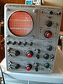
The Tektronix 502 is a dual-beam oscilloscope introduced in 1958, followed by the 502A in 1963. There is also a rack-mount model, the RM502A.
Both beams have differential inputs. The horizontal deflection plates are common to both beams.
Mod 104 on a 502 provides single sweep lockout. This feature is standard on the 502A, which also has beam finder switches for each channel.
A recessed switch in the left side panel allows the upper beam amplifier to be connected to the horizontal deflection plates for single-beam X-Y operation, providing a differential X input with the same sensitivity as the Y channel. The upper beam is positioned off screen in this mode.
If the combination of time base setting and magnification selector results in a sweep faster than 1 μs/div, the horizontal scale is not calibrated, and a lamp on the front panel lights up to remind the operator of that.
Key Specifications
| Deflection | 100 μV/cm to 20 V/cm, 1−2−5, ±3% |
|---|---|
| Bandwidth | 1 MHz @ 200 mV/cm and above; 400 kHz @ 50 mV/cm, 200 kHz @ 5 mV/cm, 100 kHz @ 200 μV/cm |
| CMRR | 502A: 40,000:1 @ 100 mV/cm and 1 kHz |
| Input impedance | 1 MΩ // 47 pF |
| Sweep | 1 μs/cm to 5 s/cm, 1−2−5, ±3%; magnifier ×2, ×5, ×10 or ×20 |
| CRT | Early 502: Type T60P2/T502P2/T5020P2; Late 502, 502A: Type T5021P2; (P1, P7 or P11 were available as options) 10 vertical and 10 horizontal 1 cm divisions 3 kV acceleration |
| Dimensions | 597 mm (23½") × 286 mm (11¼") × 381 mm (15") L×W×H |
| Weight | 23.6 kg (52lb) |
Prices
| Year | 1959 | 1961 | 1963 (A) | 1971 (A) |
|---|---|---|---|---|
| Catalog price | $825 | $825 | $1,050 | $1,265 |
| 2018 value | $7,070 | $6,890 | $8,560 | $7,790 |
Internals
The −150 V supply uses a 5651 voltage reference tube as its reference.
The 6.2 VDC heater supply for the tubes in the first stage differential amplifier is transistor-regulated. This heater supply uses the −150 V supply as its reference.
There is no post-deflection acceleration. The CRT cathode voltage is −2.9 kV.
The early 502 uses a single supply for the upper beam and lower beam CRT cathodes (HV transformer 120-114). Later models (1959+, see 070-090) and the 502A have separate supplies for the two CRT cathodes (HV transformer 120-150). This improvement allows slight differences in horizontal CRT sensitivity between the two beams to be cancelled out in step 8 of the calibration procedure.
Later 502A models have a solid state (plus nuvistor) input stage, a 6DJ8 as the deflection amplifier, and transistors as amplifiers and emitter followers (only in the newest version).
The 502 has a 123 °F (50.5 °C) thermal cutoff switch.
Links
- Tektronix 502A @ amplifier.cd (many internal pictures)
- Tektronix 502A internals @ youtube (German)
Pictures
502
-

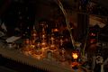
502 with (single-beam) X-Y display
-
502 Mod.104 (single sweep), front
-

502 Mod.104 (single sweep), front from lower left
-
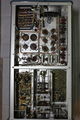
502 left interior
-
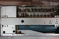
502 right interior
-
rubber shock mount of amplifier sub-chassis
-
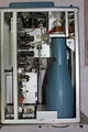
502 bottom
-
502 trace
-
502 trace
-
502 front panel without knobs
-
502 power supply section in operation


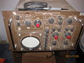
502A
-
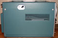
502A
-

502A right internal
-
502A right
-
502A left
-
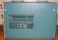
502A rear
-
Solid-state input stage with two 6DJ*
-
502A vertical amp sn 25,997 to 30,999


RM502A
-
RM502A
-
RM502A rear
-
RM 502A
-
RM 502A display
-
RM 502A bottom
-
RM 502A transformer wiring
-
RM 502A top
-
RM 502A vibration-isolated vertical amp


Third version 502A, serial number ≥31,000
-
top side lower beam input amp and attenuator, bottom side of upper beam vert input board
-
late model RM502A
-
late model RM502A
-
late model RM502A
-
late model RM502A
-

late model RM502A
-
late model RM502A
-
late model RM502A


