7854/Repairs: Difference between revisions
(Added pictures of a replacement board) |
No edit summary |
||
| (4 intermediate revisions by the same user not shown) | |||
| Line 1: | Line 1: | ||
==Mask ROM deterioration== | |||
In the following, we attempt to outline all of the possible remediation techniques to address the mask ROM problem that plagues 7854 scopes with the original ROM board. Later versions (Serial B100000 and above) have a combined RAM/ROM/Backup board which occupied the larger RAM slot, forward of the ROM slot. Note the serial number delineation is mentioned in the service manual, though there is at least one report of a user with a slightly later serial (#B100078) that had the original configuration. | |||
The ROM board, A31, contains: | The ROM board, A31, contains: | ||
| Line 9: | Line 11: | ||
The FPLA watches all 15 address lines and outputs 6 address lines and a flag. When an address is called that has a newer segment of code on the EPROMs, the FPLA decodes the incoming address, puts an altered address on the board’s bus, and sets a flag that switches the chip selects from the main ROM to the patch EPROMs. The patch itself is only a few words, enough to jump to another part of the EPROM where a new segment of code resides. The EPROMs also contains ‘normal’ code that is directly addressed. | The FPLA watches all 15 address lines and outputs 6 address lines and a flag. When an address is called that has a newer segment of code on the EPROMs, the FPLA decodes the incoming address, puts an altered address on the board’s bus, and sets a flag that switches the chip selects from the main ROM to the patch EPROMs. The patch itself is only a few words, enough to jump to another part of the EPROM where a new segment of code resides. The EPROMs also contains ‘normal’ code that is directly addressed. | ||
The mask ROMs are | The mask ROMs are | ||
U200 160-0410-00 / 160-0410-01 | * U100: 160-0408-00 / 160-0408-01 | ||
* U110: 160-0409-00 / 160-0409-01 | |||
* U200: 160-0410-00 / 160-0410-01 | |||
* U210: 160-0411-00 / 160-0411-01 | |||
The difference between the -00 and -01 versions appears to be only the change in vendor from Mostek to Motorola. | |||
The contents are identical. | |||
The FPLA & patch EPROMs have -00, -01, and -02 versions. | |||
The FPLA & EPROM versions must match each other. | |||
===Option 1: Programming pin-compatible EPROMs with original images=== | |||
This approach uses the original images, and relies on a working FPLA, and matching patch EPROMs. You can use either (4) MCM68766C35 or CY7C64 EPROMs, and the -00 images on the [[ROM images]] page. In the case of the MCM68766 EPROMs, the 'C35' suffix is important, as it denotes the access speed. Several people have confirmed that 350 ns EPROMs are necessary and have reported intermittent issues in using 400 ns chips. These EPROMs are out of production, and are not programmable on inexpensive USB programmers. | |||
This approach uses the original images, and relies on a working FPLA, and matching patch EPROMs. You can use either (4) MCM68766C35 or CY7C64 EPROMs, and the -00 images on the [[ | |||
This is a good option for initial troubleshooting, but as it relies on a working FPLA, may still be prone to future issues. The stability of the FPLAs is somewhat unknown, though there have been reports of them being a source of trouble. | This is a good option for initial troubleshooting, but as it relies on a working FPLA, may still be prone to future issues. The stability of the FPLAs is somewhat unknown, though there have been reports of them being a source of trouble. | ||
===Option 2: Programming pin-compatible EPROMs with patched images=== | |||
Most solutions that have been described elsewhere involve the use of patched images, which already include the patch terms. This mostly obviates the need for the FPLA (in fact it must be removed unless you have a -02 version), but still requires the -02 patch EPROMs. | Most solutions that have been described elsewhere involve the use of patched images, which already include the patch terms. This mostly obviates the need for the FPLA (in fact it must be removed unless you have a -02 version), but still requires the -02 patch EPROMs. | ||
| Line 38: | Line 37: | ||
[[Media:Tek7854_patched_for_8k.zip|This file]] from David DiGiacomo contains the images required. | [[Media:Tek7854_patched_for_8k.zip|This file]] from David DiGiacomo contains the images required. | ||
===Option 3: Programming 28 pin EPROMs with combined images=== | |||
This is the solution [https://vintagetek.org/7854-mostek-mkb36000-rom-repairs documented on the Vintage Tek Museum’s page], and requires (2) 27128A 16k EPROMs, which are also out of production, but easier to acquire and program. Using a pair of 16k EPROMs covers the address space of 4 original 8k ROMs. These require adapter sockets, which may or may not interfere with the ability to retain the GPIB board, depending on who you ask. As with the above option, if you have anything other than -02 version EPROMs, you must replace those as well with (2) 2716-1 EPROMs. You must also rewire A13 & Chip Select lines now that the address space is handled by 2 chips instead of 4. From the Tek Museum’s page: | |||
This is the solution [https://vintagetek.org/7854-mostek-mkb36000-rom-repairs documented | |||
''Option 2: (We have not implemented this so consider it unverified) Cut and lift U420 pins 9 and 13. They will float high or you can connect these pins to +5V.'' | :''Wire A13 by connecting both 27128 pin 26 to U425 pin 1.'' | ||
:''Wire new CS. Start by disconnecting the existing CS from U200 and U210 pin 20. We did this by simply not connecting pin 22 in the EPROM adapter (which connects to pin 20 on the PCB) and then flying a new CS wire directly to pin 22 of the EPROM:'' | |||
::''Option 1: Add an unused gate by connecting both 27128 U200 and U210 pin 22 to U225 pin 11. Connect U320 pin 13 to U225 pins 12 and 13'' | |||
::''Option 2: (We have not implemented this so consider it unverified) Cut and lift U420 pins 9 and 13. They will float high or you can connect these pins to +5V.'' | |||
[[Media:Tek7854_patched_for_16k.zip|This file]] from Pentti Haka contains the images required. | [[Media:Tek7854_patched_for_16k.zip|This file]] from Pentti Haka contains the images required. | ||
===Option 4: Build a new board=== | |||
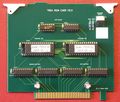
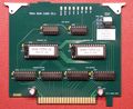
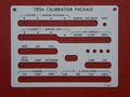
Several people have built replacement boards that use modern programmable devices. [[user:Luebben|Holger Lübben]] produced a new version of the combined ROM Diagnostic board. | |||
Several people have built replacement boards that use modern programmable devices. Holger Lübben produced a new version of the combined ROM Diagnostic board. | |||
<gallery> | <gallery> | ||
| Line 63: | Line 57: | ||
7854_dignostic_ovl.jpg|Keyboard overlay | 7854_dignostic_ovl.jpg|Keyboard overlay | ||
</gallery> | </gallery> | ||
[[Category:Instrument repair reports]] | |||
Latest revision as of 03:55, 16 August 2021
Mask ROM deterioration
In the following, we attempt to outline all of the possible remediation techniques to address the mask ROM problem that plagues 7854 scopes with the original ROM board. Later versions (Serial B100000 and above) have a combined RAM/ROM/Backup board which occupied the larger RAM slot, forward of the ROM slot. Note the serial number delineation is mentioned in the service manual, though there is at least one report of a user with a slightly later serial (#B100078) that had the original configuration.
The ROM board, A31, contains:
- 16k words of ‘base code’ starting at address 0000, spanning across (4) 8k byte mask ROMs from Mostek (upper left)
- 2k words of patch code 0x8000, spanning (2) 2k byte EPROMs (upper right)
- A Field Programmable Logic Array (FPLA) in the lower left
The FPLA watches all 15 address lines and outputs 6 address lines and a flag. When an address is called that has a newer segment of code on the EPROMs, the FPLA decodes the incoming address, puts an altered address on the board’s bus, and sets a flag that switches the chip selects from the main ROM to the patch EPROMs. The patch itself is only a few words, enough to jump to another part of the EPROM where a new segment of code resides. The EPROMs also contains ‘normal’ code that is directly addressed.
The mask ROMs are
- U100: 160-0408-00 / 160-0408-01
- U110: 160-0409-00 / 160-0409-01
- U200: 160-0410-00 / 160-0410-01
- U210: 160-0411-00 / 160-0411-01
The difference between the -00 and -01 versions appears to be only the change in vendor from Mostek to Motorola. The contents are identical. The FPLA & patch EPROMs have -00, -01, and -02 versions. The FPLA & EPROM versions must match each other.
Option 1: Programming pin-compatible EPROMs with original images
This approach uses the original images, and relies on a working FPLA, and matching patch EPROMs. You can use either (4) MCM68766C35 or CY7C64 EPROMs, and the -00 images on the ROM images page. In the case of the MCM68766 EPROMs, the 'C35' suffix is important, as it denotes the access speed. Several people have confirmed that 350 ns EPROMs are necessary and have reported intermittent issues in using 400 ns chips. These EPROMs are out of production, and are not programmable on inexpensive USB programmers.
This is a good option for initial troubleshooting, but as it relies on a working FPLA, may still be prone to future issues. The stability of the FPLAs is somewhat unknown, though there have been reports of them being a source of trouble.
Option 2: Programming pin-compatible EPROMs with patched images
Most solutions that have been described elsewhere involve the use of patched images, which already include the patch terms. This mostly obviates the need for the FPLA (in fact it must be removed unless you have a -02 version), but still requires the -02 patch EPROMs.
You can again use either (4) MCM68766C35 or CY7C64 EPROMs to replace the mask ROMs, and if you have anything other than -02 version EPROMs, you must replace those as well with (2) 2716-1 EPROMs.
This file from David DiGiacomo contains the images required.
Option 3: Programming 28 pin EPROMs with combined images
This is the solution documented on the Vintage Tek Museum’s page, and requires (2) 27128A 16k EPROMs, which are also out of production, but easier to acquire and program. Using a pair of 16k EPROMs covers the address space of 4 original 8k ROMs. These require adapter sockets, which may or may not interfere with the ability to retain the GPIB board, depending on who you ask. As with the above option, if you have anything other than -02 version EPROMs, you must replace those as well with (2) 2716-1 EPROMs. You must also rewire A13 & Chip Select lines now that the address space is handled by 2 chips instead of 4. From the Tek Museum’s page:
- Wire A13 by connecting both 27128 pin 26 to U425 pin 1.
- Wire new CS. Start by disconnecting the existing CS from U200 and U210 pin 20. We did this by simply not connecting pin 22 in the EPROM adapter (which connects to pin 20 on the PCB) and then flying a new CS wire directly to pin 22 of the EPROM:
- Option 1: Add an unused gate by connecting both 27128 U200 and U210 pin 22 to U225 pin 11. Connect U320 pin 13 to U225 pins 12 and 13
- Option 2: (We have not implemented this so consider it unverified) Cut and lift U420 pins 9 and 13. They will float high or you can connect these pins to +5V.
This file from Pentti Haka contains the images required.
Option 4: Build a new board
Several people have built replacement boards that use modern programmable devices. Holger Lübben produced a new version of the combined ROM Diagnostic board.
-
Prototype
-
Final version
-
Keyboard overlay


