TU-3: Difference between revisions
Jump to navigation
Jump to search
No edit summary |
No edit summary |
||
| (2 intermediate revisions by 2 users not shown) | |||
| Line 1: | Line 1: | ||
{{Plugin Sidebar | |||
|manufacturer=Tektronix | |||
|series=580-series scopes | |||
|type= | |||
|summary=calibration fixture | |||
|image=Tek tu-3 1.jpg | |||
|caption=Tek TU-3 | |||
|introduced=(?) | |||
|discontinued=(?) | |||
|designers= | |||
|manuals= | |||
* [[Media:070-293.pdf|Tektronix TU-3 Manual]] (OCR) | |||
* [[Media:Tek tu-3.pdf|Tektronix TU-3 Instrument Reference Book]] (OCR) | |||
}} | |||
The '''Tektronix TU-3''' is a calibration fixture plug-in for [[580-series scopes]] that was replaced by the [[84|Type 84]] which additionally contains a pulser to adjust vertical step response. | The '''Tektronix TU-3''' is a calibration fixture plug-in for [[580-series scopes]] that was replaced by the [[84|Type 84]] which additionally contains a pulser to adjust vertical step response. | ||
| Line 7: | Line 21: | ||
The cathode followers decouple the input signal from the oscilloscope vertical amplifier and elevate the vertical amplifier input to the required voltage (about +50 volts). | The cathode followers decouple the input signal from the oscilloscope vertical amplifier and elevate the vertical amplifier input to the required voltage (about +50 volts). | ||
==Photos== | ==Photos== | ||
<gallery> | <gallery> | ||
Tek tu-3 photo.jpg | Tek tu-3 1.jpg | ||
Tek tu-3 2.jpg | |||
Tek tu-3 3.jpg | |||
Tek tu-3 4.jpg | |||
Tek tu-3 5.jpg | |||
Tek tu-3 6.jpg | |||
Tek tu-3 7.jpg | |||
Tek tu-3 photo.jpg|Manual photo | |||
</gallery> | </gallery> | ||
[[Category:Calibration fixtures]] | [[Category:Calibration fixtures]] | ||
Latest revision as of 05:27, 13 August 2023
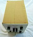
The Tektronix TU-3 is a calibration fixture plug-in for 580-series scopes that was replaced by the Type 84 which additionally contains a pulser to adjust vertical step response.
The TU-3 consists of dummy loading resistors, two cathode followers, and a bistable multivibrator.
The dummy loading resistors are connected to each regulated supply of the oscilloscope when the LOAD switch is set to HIGH, to test for the maximum power supply loading condition.
The cathode followers decouple the input signal from the oscilloscope vertical amplifier and elevate the vertical amplifier input to the required voltage (about +50 volts).
Photos
-
-
-
-
-
-
-
-
Manual photo


