155-0053-00: Difference between revisions
Jump to navigation
Jump to search
No edit summary |
No edit summary |
||
| (6 intermediate revisions by 3 users not shown) | |||
| Line 1: | Line 1: | ||
{{Hybrid IC | |||
|Manufacturer=Tektronix | |||
|Model=155-0053-00 | |||
|Part_nos=155-0053-00 | |||
|Description=sampler | |||
|Used_in=S-6 | |||
|Designers=George Frye | |||
}} containing six ultrafast Schottky diodes as well as laser-trimmed resistors. | |||
It is used in the [[S-6|S-6 feedthrough sampling head]]. | It was designed by [[George Frye]] and is used in the [[S-6|S-6 feedthrough sampling head]]. | ||
The Schottky diodes have a breakdown voltage >5 V, a dynamic resistance < 12 Ω (forward current of 10 mA) and a 0 V capacitance < 0.15 pF. | |||
{{MissingSpecs}} | |||
==Pictures== | ==Pictures== | ||
| Line 7: | Line 18: | ||
155-0053-00 1.JPG | Bottom view | 155-0053-00 1.JPG | Bottom view | ||
155-0053-00 2.JPG | Top view | 155-0053-00 2.JPG | Top view | ||
155-0053-00 3.JPG | Bottom View | 155-0053-00 3.JPG | Bottom View. Signal in/out connectors to the left, sampling pulse inputs to the right. | ||
155-0053-00 4.JPG | Interior view on ceramic substrate (connectors removed) | 155-0053-00 4.JPG | Interior view on ceramic substrate (connectors removed) | ||
S-6_Hybrid_closeup.jpg | Interior view, different resistor geometry | |||
155-0053-00 circuit.png | Circuit diagram | 155-0053-00 circuit.png | Circuit diagram | ||
</gallery> | </gallery> | ||
Latest revision as of 03:18, 19 September 2023
The Tektronix 155-0053-00 is a sampler hybrid integrated circuit containing six ultrafast Schottky diodes as well as laser-trimmed resistors.
It was designed by George Frye and is used in the S-6 feedthrough sampling head.
The Schottky diodes have a breakdown voltage >5 V, a dynamic resistance < 12 Ω (forward current of 10 mA) and a 0 V capacitance < 0.15 pF.
Key Specifications
- please add
Pictures
-
Bottom view
-
Top view
-
Bottom View. Signal in/out connectors to the left, sampling pulse inputs to the right.
-
Interior view on ceramic substrate (connectors removed)
-
Interior view, different resistor geometry
-
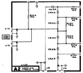
Circuit diagram


