7L5/Repairs: Difference between revisions
No edit summary |
mNo edit summary |
||
| (7 intermediate revisions by 2 users not shown) | |||
| Line 1: | Line 1: | ||
==Intermittent Rotary Encoder== | |||
The "Dot Frequency" and "Reference Level" rotary encoders can become faulty to the point that they either do not work at all, or just cause random unpredictable changes when operated. The good news is that they are mechanical switches constructed from hard gold contact traces on the front panel PCB, and all elements are held together by screws. They can be accessed by separating the front panel from the 7L5 and removing the front panel overlay. Simply cleaning the gold traces on the PCBs with isopropyl alcohol and carefully bending the contact fingers slightly outward to reestablish contact force will restore operation. See the figures below. | |||
==Front Panel Disassembly== | |||
The [[7L5]] is constructed of two main modules and the front panel assembly. The left module hinges outwards once a few screws are removed, and with further screw removal the complete front panel assembly comes off. When further disassembling the front panel, note the unconventional "Frequency Span" and "Time/Div" switches that need to be removed to be able to lift off the front panel overlay. These are entirely built into the particular knobs and can be pulled off from the front panel as a complete unit after removing two fasteners at the back. Note that the "Time/Div" switch has very thin metal contact fingers that fit into a socket at the front panel PCB. To guide installation, there is a little plastic spacer with conical holes for those pins. Make sure to install this spacer in the right orientation before attempting to reinstall the "Time/Div" switch, as shown in the figures. | |||
==Front Panel== | ==Pictures== | ||
===Front Panel=== | |||
<gallery> | <gallery> | ||
7L5_Frontpanel_PCB_back.jpg| | 7L5_FrontpanelOverlay.jpg |Front panel Overlay (Military version without B-(save A) ) | ||
7L5_Frontpanel_PCB_front_inFrame.jpg | Front panel with overlay removed in frame | |||
7L5 Frontpanel PCB back Ref Level disassembled.jpg | | 7L5_Frontpanel_PCB_back_inframe.jpg | Front panel backside in frame | ||
7L5_Frontpanel_PCB_front.jpg | Front panel frontside | |||
7L5_Frontpanel_PCB_back.jpg|Front panel backside | |||
7L5_Frontpanel_PCB_back_Ref_Level_part_disassembled.jpg | Front panel backside with Reference Level switch partially disassembled | |||
7L5 Frontpanel PCB back Ref Level disassembled.jpg | Front panel backside with Reference Level switch removed. Parts of switch with sliding contacts shown below. | |||
7L5_Frontpanel_PCB_front_Ref_Level_part_disassembled.jpg| Front panel frontside with Reference Level switch removed. Switch gold contact traces visible | |||
7L5_Span_and_time_div_switches1.jpg| Span and Time/Div. switch backsides | |||
7L5_Span_and_time_div_switches2.jpg| Span and Time/Div. switch sideview | |||
TimeDivSpacer.jpg| Front panel with Time/Div. switch removed. Note plastic spacer on the right | |||
TimeDivSpacer_installed.jpg|Front panel plastic spacer for Time/Div. switch installed in correct orientation, ready for switch installation. | |||
</gallery> | </gallery> | ||
==Left Module== | ===Left Module=== | ||
<gallery> | <gallery> | ||
7L5_left_module.jpg | 7L5_left_module.jpg | ||
| Line 22: | Line 31: | ||
</gallery> | </gallery> | ||
==Right Module== | ===Right Module=== | ||
<gallery> | <gallery> | ||
7L5_right_module_front.jpg | 7L5_right_module_front.jpg | ||
7L5_right_module_left.jpg | 7L5_right_module_left.jpg | ||
7L5_right_module_right.jpg | |||
7L5_right_module_top1.jpg | |||
</gallery> | </gallery> | ||
[[Category:Instrument repair reports]] | |||
Latest revision as of 02:46, 7 January 2023
Intermittent Rotary Encoder
The "Dot Frequency" and "Reference Level" rotary encoders can become faulty to the point that they either do not work at all, or just cause random unpredictable changes when operated. The good news is that they are mechanical switches constructed from hard gold contact traces on the front panel PCB, and all elements are held together by screws. They can be accessed by separating the front panel from the 7L5 and removing the front panel overlay. Simply cleaning the gold traces on the PCBs with isopropyl alcohol and carefully bending the contact fingers slightly outward to reestablish contact force will restore operation. See the figures below.
Front Panel Disassembly
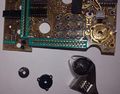
The 7L5 is constructed of two main modules and the front panel assembly. The left module hinges outwards once a few screws are removed, and with further screw removal the complete front panel assembly comes off. When further disassembling the front panel, note the unconventional "Frequency Span" and "Time/Div" switches that need to be removed to be able to lift off the front panel overlay. These are entirely built into the particular knobs and can be pulled off from the front panel as a complete unit after removing two fasteners at the back. Note that the "Time/Div" switch has very thin metal contact fingers that fit into a socket at the front panel PCB. To guide installation, there is a little plastic spacer with conical holes for those pins. Make sure to install this spacer in the right orientation before attempting to reinstall the "Time/Div" switch, as shown in the figures.
Pictures
Front Panel
-
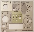
Front panel Overlay (Military version without B-(save A) )
-
Front panel with overlay removed in frame
-
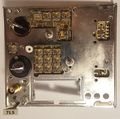
Front panel backside in frame
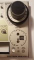
-
Front panel frontside
-
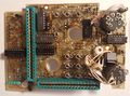
Front panel backside
-
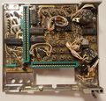
Front panel backside with Reference Level switch partially disassembled
-
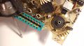
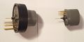
Front panel backside with Reference Level switch removed. Parts of switch with sliding contacts shown below.
-
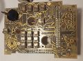
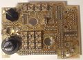
Front panel frontside with Reference Level switch removed. Switch gold contact traces visible
-

Span and Time/Div. switch backsides
-
Span and Time/Div. switch sideview
-
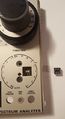
Front panel with Time/Div. switch removed. Note plastic spacer on the right
-
Front panel plastic spacer for Time/Div. switch installed in correct orientation, ready for switch installation.


