184: Difference between revisions
No edit summary |
No edit summary |
||
| (5 intermediate revisions by 2 users not shown) | |||
| Line 1: | Line 1: | ||
{{Instrument Sidebar | {{Instrument Sidebar | ||
|manufacturer= | |manufacturer=Tektronix | ||
|model=184 | |model=184 | ||
|class=Pulse generator | |class=Pulse generator | ||
|series= | |series= | ||
|summary=Time mark generator | |summary=Time-mark generator | ||
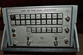
|image=Tek 184 front.JPG | |image=Tek 184 front.JPG | ||
|caption=Tek 184 front | |caption=Tek 184 front | ||
|introduced=1965 | |introduced=1965 | ||
|discontinued= | |discontinued=1971 | ||
|designers=Murlan Kaufman | |designers=Murlan Kaufman | ||
|manuals= | |manuals= | ||
* [[Media:070-0499-00.pdf|Tektronix 184 Manual]] | * [[Media:070-0499-00.pdf|Tektronix 184 Manual]] | ||
}} | }} | ||
The '''Tektronix Type 184''' is a compact crystal-controlled time mark generator, introduced in 1965 and discontinued after 1971. | The '''Tektronix Type 184''' is a compact crystal-controlled time-mark generator, introduced in 1965 and discontinued after 1971. It was replaced by the [[2901]]. | ||
The generator produces push-button selectable time marker intervals from 2 nanoseconds to 5 seconds. Multiple markers can be stacked by pressing buttons simultaneously. | |||
The task of designing the 184 was inherited and completed by [[Murlan Kaufman]]. | The task of designing the 184 was inherited and completed by [[Murlan Kaufman]]. | ||
{{BeginSpecs}} | |||
{{Spec | Marker periods | Sinusoidal 10 ns, 20 ns, 50 ns; Periodic pulses – 100 ns to 5 s in 1–5–10 sequence }} | |||
{{Spec | Output amplitude | >1 V into 50 Ω }} | |||
{{Spec | Sinusoidal HF Marker outputs | 2 ns and 5 ns at >0.3 V amplitude }} | |||
{{Spec | Marker Amplifier | positive or negative pulses, ≥25 V into 1 kΩ load for 1 μs to 5 s marks }} | |||
{{Spec | Trigger Output | 1 μs to 1 s in 1-10 sequence }} | |||
{{Spec | Accuracy and stability | Oscillator accuracy, 0.001% of 10 MHz; drift ≤3 ppm (30 Hz); both at ambient between 20°C and 30°C }} | |||
{{EndSpecs}} | |||
==Links== | |||
{{Documents|Link=184}} | |||
{{PatentLinks|184}} | |||
The 184 contains a 10 MHz crystal in a 75°C oven. | ==Internals== | ||
The | The 184 contains a 10 MHz crystal in a 75°C oven. The circuit is solid-state except for six [[7587]] Nuvistor vacuum tubes used in the 10 MHz oscillator, and the 20/50/100/500 MHz multiplier circuits. The 200 MHz stage is a passive multiplier using diodes. | ||
==Pictures== | ==Pictures== | ||
| Line 35: | Line 43: | ||
184-disabled.png | Cartoon in schematic: Disabled Man | 184-disabled.png | Cartoon in schematic: Disabled Man | ||
184-slow.png | Cartoon in schematic: Slow Sign (at [[delay line]]) | 184-slow.png | Cartoon in schematic: Slow Sign (at [[delay line]]) | ||
</gallery> | |||
==Components== | |||
{{Parts|184}} | |||
[[Category:Time mark generators]] | [[Category:Time mark generators]] | ||
Latest revision as of 05:49, 2 February 2025

The Tektronix Type 184 is a compact crystal-controlled time-mark generator, introduced in 1965 and discontinued after 1971. It was replaced by the 2901.
The generator produces push-button selectable time marker intervals from 2 nanoseconds to 5 seconds. Multiple markers can be stacked by pressing buttons simultaneously.
The task of designing the 184 was inherited and completed by Murlan Kaufman.
Key Specifications
| Marker periods | Sinusoidal 10 ns, 20 ns, 50 ns; Periodic pulses – 100 ns to 5 s in 1–5–10 sequence |
|---|---|
| Output amplitude | >1 V into 50 Ω |
| Sinusoidal HF Marker outputs | 2 ns and 5 ns at >0.3 V amplitude |
| Marker Amplifier | positive or negative pulses, ≥25 V into 1 kΩ load for 1 μs to 5 s marks |
| Trigger Output | 1 μs to 1 s in 1-10 sequence |
| Accuracy and stability | Oscillator accuracy, 0.001% of 10 MHz; drift ≤3 ppm (30 Hz); both at ambient between 20°C and 30°C |
Links
Documents Referencing 184
- (no results)
Internals
The 184 contains a 10 MHz crystal in a 75°C oven. The circuit is solid-state except for six 7587 Nuvistor vacuum tubes used in the 10 MHz oscillator, and the 20/50/100/500 MHz multiplier circuits. The 200 MHz stage is a passive multiplier using diodes.
Pictures
-
-
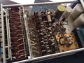
internal, top
-
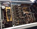
internal, bottom
-
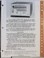
Tek 184 product announcement
-
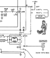
Cartoon in schematic: Disabled Man
-
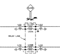
Cartoon in schematic: Slow Sign (at delay line)


Components
Some Parts Used in the 184
| Part | Part Number(s) | Class | Description | Used in |
|---|---|---|---|---|
| 7587 | 154-0465-00 | Vacuum Tube (Tetrode) | sharp-cutoff Nuvistor tetrode | 184 |