7A13: Difference between revisions
(template change) |
(pictures, description) |
||
| Line 2: | Line 2: | ||
title=Tektronix 7A13 | | title=Tektronix 7A13 | | ||
summary=100 MHz Differential Comparator | | summary=100 MHz Differential Comparator | | ||
image=Tek | image=Tek 7a13 front.jpg | | ||
caption=7A13 front panel (older version with mechanical voltage display) | | caption=7A13 front panel (older version with mechanical voltage display) | | ||
introduced= | introduced=1970. | | ||
discontinued= | discontinued=1992 | | ||
series=[[7000-series scopes]]| | series=[[7000-series scopes]]| | ||
manuals= | manuals= | ||
| Line 13: | Line 13: | ||
}} | }} | ||
The Tektronix 7A13 is a "differential comparator" vertical plug-in for [[7000-series scopes]], i.e. a fast differential amplifier with adjustable DC offset. | The '''Tektronix 7A13''' is a "differential comparator" vertical plug-in for [[7000-series scopes]], i.e. a fast differential amplifier with adjustable DC offset. It is one of the first 7000 series plugins, released along with the first scopes in 1970, and was made until the 7000 series was retired in 1992. | ||
Older versions display the comparison (offset) voltage through a mechanical dial, newer versions through an LED panel meter. | ==Operation== | ||
Older versions display the comparison (offset) voltage through a mechanical dial, newer versions (from 1976 on) through an LED panel meter. In addition, this voltage is brought out through a front panel connector so it can be measured externally. | |||
In differential mode, a +/-10 V common mode signal can be present at the inputs without attenuation. Either input can be switched to the comparison voltage, which is settable to four digits by a 10-step switch and a 10-turn potentiometer. In this comparator mode, the offset range is effectively 10,000 divisions. | |||
On the 1 mV/Div to 50 mV/Div ranges, the gate resistors can be disabled by an internal switch, raising DC input impedance to "approximately infinite" (as indicated by a front panel lamp). | |||
{{BeginSpecs}} | |||
{{Spec | Bandwidth | 100 MHz (in 7700 or faster mainframes) }} | |||
{{Spec | Rise time | 3.5 ns }} | |||
{{Spec | Deflection factor | 1 mV/Div – 5 V/Div (1–2–5 sequence) }} | |||
{{Spec | Common Mode range | at least +10 V / -10 V from 1 mV/Div to 50 mV/Div }} | |||
{{Spec | Overdrive Recovery | to within 2 mV in 1µs (at 1 mV/Div) }} | |||
{{Spec | CMRR | at least 10,000:1 for 10 V<sub>p-p</sub> or less, 100 kHz to 1 MHz, decreasing to 500:1 at 10 MHz with 1 V<sub>p-p</sub>, 200:1 at 20 MHz with 1 V<sub>p-p</sub> }} | |||
{{Spec | Input impedance | 1 MΩ // 20 pF }} | |||
{{Spec | Comparison voltage | 0 V — +/-10 V }} | |||
{{Spec | Warmup time | 5 minutes for short-term measurements, 1 hour for best stability }} | |||
{{EndSpecs}} | |||
==Internals== | |||
===Repair issues=== | |||
The 7A13 uses twelve miniature relays similar to those used in the [[7A11]]. These are very rare. The [http://www.amplifier.cd/Test_Equipment/Tektronix/Tektronix_7000_series_amplifier/amplifier_7A11.htm 7A11 repair report at apmlifier.cd] describes a possible replacement with a modern component. | |||
==Links== | ==Links== | ||
* http://www.barrytech.com/tektronix/tek7000/tek7a13.html | * [http://www.amplifier.cd/Test_Equipment/Tektronix/Tektronix_7000_series_amplifier/amplifier_7A13.htm Tek 7A13 @ amplifier.cd] | ||
* [http:// | * [http://www.barrytech.com/tektronix/tek7000/tek7a13.html Tek 7A13 @ barrytech.com] | ||
* [http://ik1zyw.blogspot.co.at/2007/09/tektronix-7a13-broken-relays.html Tex 7A13 broken relays @ IK1ZYW Labs] | |||
==Pictures== | ==Pictures== | ||
===Older version (1970-1975, mechanical meter)=== | |||
<gallery> | <gallery> | ||
File:Tek-7a13- | File:Tek 7a13 front.jpg | 7A13 older version, front view | ||
File:Tek-7a13- | File:Tek-7a13-left.jpg | 7A13, left side | ||
File:Tek-7a13-right.jpg | 7A13, right side | |||
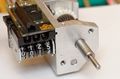
File:7a13-dials1.jpg | closeup of mechanical V<sub>C</sub> display in operation | |||
File:7a13-dials2.jpg | Three light bulbs above the digit dials for decimal point indication | |||
File:7a13-gears1.jpg | Gear mechanism | |||
File:7a13-gears2.jpg | Gear mechanism. If the leftmost display digit is misaligned with respect to the switch position, the left pair of bevel gears seen here need to be rotated relatively to each other. | |||
</gallery> | </gallery> | ||
===Newer version (1976-1992, LED meter)=== | |||
<gallery> | |||
File:Tek-7a13-2.jpg | 7A13 newer version, front view | |||
</gallery> | |||
[[Category:7000 series vertical plugins]] | [[Category:7000 series vertical plugins]] | ||
Revision as of 07:28, 7 December 2014
The Tektronix 7A13 is a "differential comparator" vertical plug-in for 7000-series scopes, i.e. a fast differential amplifier with adjustable DC offset. It is one of the first 7000 series plugins, released along with the first scopes in 1970, and was made until the 7000 series was retired in 1992.
Operation
Older versions display the comparison (offset) voltage through a mechanical dial, newer versions (from 1976 on) through an LED panel meter. In addition, this voltage is brought out through a front panel connector so it can be measured externally.
In differential mode, a +/-10 V common mode signal can be present at the inputs without attenuation. Either input can be switched to the comparison voltage, which is settable to four digits by a 10-step switch and a 10-turn potentiometer. In this comparator mode, the offset range is effectively 10,000 divisions.
On the 1 mV/Div to 50 mV/Div ranges, the gate resistors can be disabled by an internal switch, raising DC input impedance to "approximately infinite" (as indicated by a front panel lamp).
Key Specifications
| Bandwidth | 100 MHz (in 7700 or faster mainframes) |
|---|---|
| Rise time | 3.5 ns |
| Deflection factor | 1 mV/Div – 5 V/Div (1–2–5 sequence) |
| Common Mode range | at least +10 V / -10 V from 1 mV/Div to 50 mV/Div |
| Overdrive Recovery | to within 2 mV in 1µs (at 1 mV/Div) |
| CMRR | at least 10,000:1 for 10 Vp-p or less, 100 kHz to 1 MHz, decreasing to 500:1 at 10 MHz with 1 Vp-p, 200:1 at 20 MHz with 1 Vp-p |
| Input impedance | 1 MΩ // 20 pF |
| Comparison voltage | 0 V — +/-10 V |
| Warmup time | 5 minutes for short-term measurements, 1 hour for best stability |
Internals
Repair issues
The 7A13 uses twelve miniature relays similar to those used in the 7A11. These are very rare. The 7A11 repair report at apmlifier.cd describes a possible replacement with a modern component.
Links
Pictures
Older version (1970-1975, mechanical meter)
-
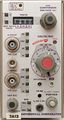
7A13 older version, front view
-
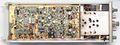
7A13, left side
-
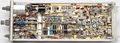
7A13, right side
-
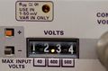
closeup of mechanical VC display in operation
-
Three light bulbs above the digit dials for decimal point indication
-
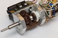
Gear mechanism
-
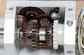
Gear mechanism. If the leftmost display digit is misaligned with respect to the switch position, the left pair of bevel gears seen here need to be rotated relatively to each other.


Newer version (1976-1992, LED meter)
-
7A13 newer version, front view