7A11

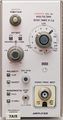
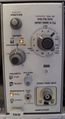
The Tektronix 7A11, introduced in 1969, is a vertical plug-in for 7000-series scopes.
It includes a permanently attached FET probe. The bandwidth of a 7A11 in a 7904 is 250 MHz. The front-end FET is a 151-1034-00.
The probe can be used with a front panel BNC connector or the probe cable can be unwound from the plugin in six steps to a maximum of 7 feet in length.
The 7A11 contains a selectable three-pole 20 MHz bandwidth limit filter.
The designers were John Addis, Ron Peltola, and Glenn Bateman.
Key Specifications
| Bandwidth | 250 MHz (in 7903, R7903, 7904, 7104) |
|---|---|
| Deflection | 5 mV/Div to 20 V/Div, 1–2–5 |
| Input resistance | 1 MΩ |
| Input capacitance |
|
| Features |
|
Links
Documents Referencing 7A11
| Document | Class | Title | Authors | Year | Links |
|---|---|---|---|---|---|
| Tekscope 1969 V1 N5 Oct 1969.pdf | Article | Introducing the New Generation | 1969 | 7000-series scopes • 7504 • 7704 • 7A11 • 7A12 • 7A13 • 7A14 • 7A16 • 7A22 • 7S11 • 7M11 • 7B50 • 7B51 • 7B70 • 7B71 • 7T11 • R5030 • 7000 series readout system • Miniature relays • Cam switches • Industrial Design • T7500 • T7700 • P6052 • P6053 • C-50 • C-51 • 204-2 | |
| Tekscope 1969 V1 N6 Dec 1969.pdf | Article | A New Logic for Oscilloscope Displays | 1969 | 7000-series scopes • 7A11 • 7A12 • 7A13 • 7A14 • 7A16 • 7A22 • 7B50 • 7B51 • 7B70 • 7B71 • 7S11 • 7T11 • 7504 • 7704 | |
| 7000 series brochure March 1973.pdf | Brochure | 7000 series brochure, March 1973 | 1973 | 7A11 • 7A12 • 7A13 • 7A14 • 7A15A • 7A16A • 7A17 • 7A18 • 7A19 • 7A21N • 7A22 • 7B50 • 7B53A • 7B70 • 7B71 • 7B92 • 7CT1N • 7D11 • 7D13 • 7D14 • 7D15 • 7M11 • 7L12 • 7S11 • 7S12 • 7T11 • 7704A • R7704 • 7904 • R7903 • 7603 • R7603 • 7403N • R7403N • 7313 • R7313 • 7613 • R7613 • 7623 • R7623 • P7001 |
Internals
Regarding the 7A11, its designer John Addis says:
The 7A11 input capacitance is 5.8 pF from 5 mV/Div to 50 mV/Div, goes down to 3.4 pF from 100 mV/Div to 1 V/Div, and down again to 2.0 pF from 2 V/Div to 20 V/Div. Because the AC coupling is attained with a plug-on capacitor (that adds 1.2 pF to the input C), a DC offset is supplied to reduce the need for AC coupling.
A nice thing about the 7A11 was that the probe cable length was adjustable in six steps to just over 7 feet in length. You just uncoil however much cable length you want.
The 7A11 was admittedly clumsy to use because of the probe size. It had some trouble — DC drift, RF pickup at 5 mV, 100 mV and 2 V/Div. It was not very popular partially because it was expensive, $850 for single channel vs. dual channel 7A12 (105 MHz) at $700. But there was never another 1 MΩ 7000-series plugin as fast as the 7A11 ... and it was one of the originals!
The 7A16 (single channel plugin) was also 150 MHz, but that was a year later. Then the 7904 came out in late 1971. That made the 7A11 a 250 MHz plugin (for $950). The 7A16 was then 225 MHz (for $625). The 7A16 disappeared rapidly and became the 7A16A, still 225 MHz in 1973.
In 1972, the 485 came out with a 250 MHz, 1 MΩ input. The 485 used a faster IC process ("SH2", 3.5 GHz) than was available for first generation 7K instruments but the 485's 1 MΩ to 50 Ω converter used only discrete devices. (See Electronics June, 1972.)
By 1974, the 7A11 cost $950 and the new, popular 7A26 (dual trace) was $1,050, not counting probes. But that would still only get you to 50 mV/div with a (9.5 pF, 3 foot, × 10) probe, five years after the 7A11 introduction. Tom Rousseau designed the 7A26 which used the faster SH-2 IC process and a vertical IC I designed for the 485. The 7A26 sold so well that Tektronix presented Tom with an entirely gold plated 7A26! Obviously, he still has it.
Remember also that the 7A11 was introduced at the same show as the HP183A/1830A/1840A, faster (250 MHz), smaller, lighter, and less expensive with better triggering than 7000 series had. Their secrets were Al DeVilbiss and a faster IC process. We had neither.
The star-crossed 7A12 designed by Roy Hayes, which was supposed to be the dual trace flagship of the original plugins, was only 105 MHz, not the hoped-for 150 MHz. That was partially due to the fact that it used the existing Tek IC process (about 1 GHz). That was a bad decision on day one. The HP IC process was about 3 GHz. The 7A11 used discrete NPN and PNP transistors with 4 GHz ft.
There is one noteworthy point I would like to make about the 7A11. In those days, the different V/div settings were generally attained using fixed high impedance attenuators, usually stacked one after another and few with more than ×10 attenuation. I wanted the 7A11 to be able to handle the full useful range of sensitivites that other plugins attained when adding a ×10 probe ... that meant going to 20 V/Div. But you could certainly get to 5 mV/Div, which you could not attain with a 5 mV/Div plugin and a ×10 passive probe.
But using that scheme, if the 7A11 went to 20 V/Div, it would have to stack three ×10 attenuators inside the probe, making it a behemoth, and even if you did, that would still leave the ×2 and ×5 attenuations up to gain switching in the amplifier.
Problem with gain switching is, the bandwidth and transient response tend to change when you change amplifier gain. If gain switching was accomplished by changing emitter resistors, dc balance changed with every gain change. That meant that the VAR gain control and fixed gain selection required two dc balance controls. That would be unpleasant (see 7A13). The greater the gain change, the greater the bandwidth/transient response change in the amplifier. The more gain settings you had, the worse it got due to longer leads and more parasitics.
To get a 1-2-5 sequence from 5 mV/Div to 20 V/Div, it had the worst of all possible worlds. The 7A11 needed two ×20 attenuators in the probe and that meant that it needed not just ×1, ×2 and ×5 gains in the amplifier, but ×1, ×2, ×2.5, ×4, ×5 and ×10! This had not been done before, but the 7A11 does it without any change in transient response!
The secret is three entirely passive, relay-switched, O-pad attenuators: ×2, ×2, and ×2.5 in a balanced transmission line environment. Stack them up (as you can do with matched pads) and you get all the combinations you need: ×1, ×2, ×2.5, ×4, ×5, and ×10. From 5 mV/Div to 20 V/Div, twelve different V/div settings, more than any other high speed plug in!
I got a patent on the variable attenuator, which was just a JFET shunting the O-pads. The patent had to do with making the gain vs. control rotation linear, which does not simply happen with linear gate-source voltage control. The JFET causes a small change in transient response, but not a bad one.
Ron Peltola (of Peltola connector fame) designed the probe attenuator, Glenn Bateman and Ron designed the probe amplifier. I helped a little on the probe amplifier.
The group that did the probe design was Ken Holland's High Frequency Component Design Group. Ron Peltola was the engineer.
Links
- Tek 7A11 page @ barrytech.com (waybackarchive)
- Tek 7A11 page @ amplifier.cd including repair report (relay replacement!)
Prices
| Year | 1971 | 1980 | 1984 |
|---|---|---|---|
| Catalog price | $850 | $1,725 | $2,700 |
| 2023 value | $6,400 | $6,400 | $7,900 |
Pictures
-
-
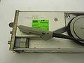
right side, probe unplugged
-
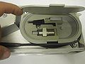
probe accessoires: tip cover, AC coupling capacitor, GR-874 adapter (017-0088-00)
-
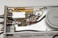
right side detail, cover removed
-
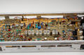
left side detail, cover removed
-
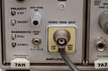
input jack with probe cable
-
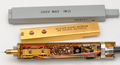
interior of probe
-
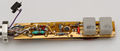
interior of probe, back side with range relays
-
-
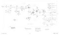
Probe
-
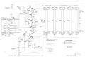
Input Amplifier
-
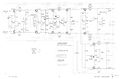
Output Amplifier
-
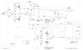
Offset Generator
-
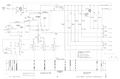
Volts/Div Switch and Readout
-
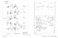
Power Supply and Output Connectors


Components
Some Parts Used in the 7A11
| Part | Part Number(s) | Class | Description | Used in |
|---|---|---|---|---|
| 148-0034-00 | 148-0034-00 | Discrete component | miniature DPDT relay | 5A48 • 7A11 • 7A13 • 7A14 • 7B70 • 7B71 • 7503 • 7904 • 7904A |
| 148-0034-03 | 148-0034-03 | Discrete component | miniature DPDT relay | 7A11 |
| 148-0058-00 | 148-0058-00 | Discrete component | miniature SPDT relay | 7A11 |
| 151-1034-00 | 151-1034-00 | Discrete component | dual N-channel JFET | 7A11 • P6051 |