5CT1N: Difference between revisions
Jump to navigation
Jump to search
No edit summary |
No edit summary |
||
| Line 13: | Line 13: | ||
* [http://w140.com/smb/7ct1n_sm.pdf Tektronix 7CT1N Manual (OCR, PDF)] | * [http://w140.com/smb/7ct1n_sm.pdf Tektronix 7CT1N Manual (OCR, PDF)] | ||
}} | }} | ||
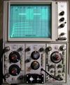
The '''Tektronix 5CT1N''' is a | The '''Tektronix 5CT1N''' is a curve tracer plug-in for the 5000 series oscilloscopes, similar to the [[7CT1N]] for [[7000-series scopes]]. | ||
{{BeginSpecs}} | {{BeginSpecs}} | ||
| Line 42: | Line 42: | ||
==Pictures== | ==Pictures== | ||
<gallery> | <gallery> | ||
5440.jpg | 5Ct1N in [[5440]] mainframe vertical bay, X output connected to time base X input | |||
Tek-5ct1_in_use.jpg| Displaying transistor curves | |||
Tek 5ct1n f1.JPG | |||
</gallery> | </gallery> | ||
==Common Problems== | ==Common Problems== | ||
C30 and C32 ( | C30 and C32 (100 μF, 25 V) [http://hakanh.com/dl/docs/hardtofind/CT1N.pdf are under-rated] and therefore have a tendency to leak or short, | ||
causing associated resistors R30 and R32 (240 Ω, 0.25W, 5%) to overheat and fail. C30 and C32 should be replaced with modern equivalents rated at 63 V. | |||
[[Category:Curve tracers]] | [[Category:Curve tracers]] | ||
[[Category:5000 series plugins]] | [[Category:5000 series plugins]] | ||
Revision as of 05:13, 5 December 2016
Template:Plugin Sidebar 2 The Tektronix 5CT1N is a curve tracer plug-in for the 5000 series oscilloscopes, similar to the 7CT1N for 7000-series scopes.
Key Specifications
| DUT drive voltage (C-E) |
|
|---|---|
| DUT current display |
|
| Base/Gate drive |
|
| DUT connection | Three 4 mm jacks / binding posts |
Links
Pictures
-
5Ct1N in 5440 mainframe vertical bay, X output connected to time base X input
-
Displaying transistor curves
-
Common Problems
C30 and C32 (100 μF, 25 V) are under-rated and therefore have a tendency to leak or short, causing associated resistors R30 and R32 (240 Ω, 0.25W, 5%) to overheat and fail. C30 and C32 should be replaced with modern equivalents rated at 63 V.


