514: Difference between revisions
No edit summary |
mNo edit summary |
||
| Line 14: | Line 14: | ||
It was designed by Tektronix engineers [[Bob Davis]] and [[Dick Rhiger]]. | It was designed by Tektronix engineers [[Bob Davis]] and [[Dick Rhiger]]. | ||
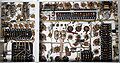
Using a three-section | Using a three-section [[distributed amplifier]], it provides frequency response from DC to 10 MHz. | ||
Prior to the 514, customers had to choose between an instrument with 10 MHz bandwidth (the [[511]]) ''or'' an instrument with DC response (the [[512]]). | Prior to the 514, customers had to choose between an instrument with 10 MHz bandwidth (the [[511]]) | ||
''or'' an instrument with DC response (the [[512]]). The 514 provides DC response ''and'' 10 MHz bandwidth. | |||
It weighs 60 pounds (27 kg) and consumes 360 W. | It weighs 60 pounds (27 kg) and consumes 360 W. | ||
The 514 uses a [[5CPA]] CRT with a total accelerating voltage of 3000 V | The 514 uses a [[5CPA]] CRT with a total accelerating voltage of 3000 V | ||
(-1.5 kV on the CRT cathode and +1.5 kV on the CRT anode) . | (-1.5 kV on the CRT cathode and +1.5 kV on the CRT anode) . | ||
The standard [[phosphor]] for a 514 was P1. | The standard [[phosphor]] for a 514 was P1. | ||
The deflection sensitivity of the CRT is approximately | The deflection sensitivity of the CRT is approximately 27 V/cm vertical and 32 V/cm horizontal. | ||
27 V/cm vertical and 32 V/cm horizontal. | |||
The power supply is regulated based on a -140 V reference produced by a [[OD3]] gas regulator tube. | The power supply is regulated based on a -140 V reference produced by a [[OD3]] gas regulator tube. | ||
The +225 V supply uses three [[5V4G]] rectifier tubes in parallel. | The +225 V supply uses three [[5V4G]] rectifier tubes in parallel. | ||
Throughout its production run, a 'D' variant was available (514D, with the 'D' being stamped in by hand on some models) which has a 24-section 250 ns lumped L-C [[delay line]]. | Throughout its production run, a 'D' variant was available (514D, with the 'D' being stamped in by hand | ||
on some models), which has a 24-section 250 ns lumped L-C [[delay line]]. | |||
There was also an 'A' version (514-A & 514-AD respectively), which appears to have been available in 1954. | There was also an 'A' version (514-A & 514-AD respectively), which appears to have been available in 1954. | ||
''(There were also some models marked 'Series A', which may have been a predecessor to the 514A? | ''(There were also some models marked 'Series A', which may have been a predecessor to the 514A? | ||
How does the 514AD differ from the 514D?)'' | |||
It has no [[thermal cutoff]]. | It has no [[thermal cutoff]]. | ||
Revision as of 15:23, 10 February 2016

The Tektronix 514 is a monolithic general-purpose oscilloscope introduced in 1949 or 1950.
It was designed by Tektronix engineers Bob Davis and Dick Rhiger.
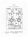
Using a three-section distributed amplifier, it provides frequency response from DC to 10 MHz. Prior to the 514, customers had to choose between an instrument with 10 MHz bandwidth (the 511) or an instrument with DC response (the 512). The 514 provides DC response and 10 MHz bandwidth.
It weighs 60 pounds (27 kg) and consumes 360 W. The 514 uses a 5CPA CRT with a total accelerating voltage of 3000 V (-1.5 kV on the CRT cathode and +1.5 kV on the CRT anode) . The standard phosphor for a 514 was P1. The deflection sensitivity of the CRT is approximately 27 V/cm vertical and 32 V/cm horizontal.
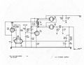
The power supply is regulated based on a -140 V reference produced by a OD3 gas regulator tube. The +225 V supply uses three 5V4G rectifier tubes in parallel.
Throughout its production run, a 'D' variant was available (514D, with the 'D' being stamped in by hand on some models), which has a 24-section 250 ns lumped L-C delay line. There was also an 'A' version (514-A & 514-AD respectively), which appears to have been available in 1954. (There were also some models marked 'Series A', which may have been a predecessor to the 514A? How does the 514AD differ from the 514D?)
It has no thermal cutoff.
Key Specifications
| Frequency response | DC to 10 MHz |
|---|---|
| Input impedance | 1 MΩ // 30 pF |
| Vertical deflection | 100 V/cm down to 300 mV/cm (DC) / 30 mV/cm (AC), 1 - 3 - 10 sequence |
| Weight | 62 pounds (28.1 kg) |
| Power consumption | 375 W |
Links
Pictures
-
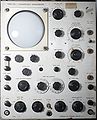
Front
-

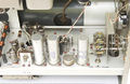
Distributed vertical amp
-
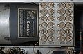
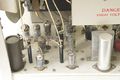
Delay line trimmer caps
-
Bottom view
-
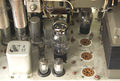
Power Supply
-

Upper Deck, rear
-
Upper Deck, front
-

Lower Deck, front
-
Lower Deck, rear
-
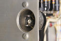
Fan Motor
-
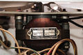
Line Socket
-
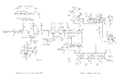
Vertical amp schematic
-
Vertical preamp, early
-
HV Power Supply, early


