7CT1N: Difference between revisions
No edit summary |
No edit summary |
||
| Line 19: | Line 19: | ||
Internally, a variable-amplitude 55 Hz triangle-wave source supplies a transformer to step up the drive voltage and | Internally, a variable-amplitude 55 Hz triangle-wave source supplies a transformer to step up the drive voltage and | ||
decouple it from ground (Emitter terminal). A step source supplies base current or gate voltage to the DUT. | decouple it from ground (Emitter terminal). A step source supplies base current or gate voltage to the DUT. | ||
The amplifier for the current axis can be switched into a | |||
The amplifier for the current axis can be switched into a ×1000 mode | |||
to detect leakage currents (of typical 1970s semiconductors, anyway). | to detect leakage currents (of typical 1970s semiconductors, anyway). | ||
{{BeginSpecs}} | {{BeginSpecs}} | ||
{{Spec | DUT drive voltage (C-E) | | {{Spec | DUT drive voltage (C-E) | | ||
* positive (NPN or N channel) or negative (PNP or P channel) half-waves | * positive (NPN or N-channel) or negative (PNP or P-channel) half-waves | ||
* 7.5 V, 0.5 V/Div, 240 mA peak | * 7.5 V, 0.5 V/Div, 240 mA peak | ||
* 30 V, 2 V/Div, 60 mA peak | * 30 V, 2 V/Div, 60 mA peak | ||
| Line 32: | Line 33: | ||
* peak power 500 mW}} | * peak power 500 mW}} | ||
{{Spec | DUT current display | | {{Spec | DUT current display | | ||
* | * 10 μA/Div to 20 mA/Div, 1−2−5 steps (×1 mode) | ||
* 10 nA/Div to | * 10 nA/Div to 20 μA/Div, 1−2−5 steps (×1000 mode)}} | ||
{{Spec | Base/Gate drive | | {{Spec | Base/Gate drive | | ||
* 0 to at least 10 steps | * 0 to at least 10 steps | ||
* dual polarity | * dual polarity | ||
* variable offset, at least +/ | * variable offset, at least +/− 5 steps | ||
* current mode: | * current mode: 1 μA/Step to 1 mA/Step in 1−2−5 sequence | ||
* voltage mode: 1 mV/ | * voltage mode: 1 mV/Step to 1 V/Step in 1−2−5 sequence (via 1 kΩ current limiting resistor) | ||
}} | }} | ||
{{Spec | DUT connection | Three 4 mm jacks / binding posts}} | {{Spec | DUT connection | Three 4 mm jacks / binding posts}} | ||
| Line 90: | Line 91: | ||
<gallery> | <gallery> | ||
tek-7ct1n-front.jpg | 7CT1N front | tek-7ct1n-front.jpg | 7CT1N front | ||
tek-7ct1n-left.jpg | tek-7ct1n-left.jpg | 7CT1N left side | ||
tek-7ct1n-right.jpg | 7CT1N right side | tek-7ct1n-right.jpg | 7CT1N right side | ||
7ct1n-bc337.jpg | 7ct1n-bc337.jpg | 7CT1N tracing a BC337 NPN Si transistor | ||
Tek 7ct1n trace.jpg | Tek 7ct1n trace.jpg | ||
Tek 7ct1n schematic2.png | Tek 7ct1n schematic2.png | ||
Tek 7ct1n td.jpg| | Tek 7ct1n td.jpg | 10 mA tunnel diode. 7A13 is set to 10 mV/div for ×10 horizontal expansion. | ||
</gallery> | </gallery> | ||
Revision as of 03:57, 4 May 2019
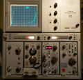
Template:Plugin Sidebar 2 The Tektronix 7CT1N is a curve tracer plug-in for 7000-series scopes. The 5CT1N plug-in for 5000-series scopes is very similar.
It can be installed in either a vertical or a horizontal compartment, a front-panel switch must be set accordingly. A pull-out cable with a plastic BNC plug connects to the input of a module installed in the corresponding plugin for the other axis, with a fixed 100 mV/Div scaling compatible with time base X inputs.
Internally, a variable-amplitude 55 Hz triangle-wave source supplies a transformer to step up the drive voltage and decouple it from ground (Emitter terminal). A step source supplies base current or gate voltage to the DUT.
The amplifier for the current axis can be switched into a ×1000 mode to detect leakage currents (of typical 1970s semiconductors, anyway).
Key Specifications
| DUT drive voltage (C-E) |
|
|---|---|
| DUT current display |
|
| Base/Gate drive |
|
| DUT connection | Three 4 mm jacks / binding posts |
| DUT adapters |
|
Links
- Tekscope Vol. 4 No. 6, Nov 1972
- Tek 7CT1N @ amplifier.cd
- Tek 7CT1N @ barrytech.com
- A homebrew test adapter
Common Problems
C30 and C32 (100 μF, 25 V) are under-rated and therefore have a tendency to leak or short, causing associated resistors R30 and R32 (240 Ω, 0.25 W, 5%) to overheat and fail. C30 and C32 should be replaced with modern equivalents rated above 35 V.
Prices
| Year | Price | 2015 value |
|---|---|---|
| 1971 | $400 | $2,320 |
| 1980 | $1,000 | $2,870 |
| 1990 | $2,100 | $3,790 |
Pictures
-
7CT1N front
-
7CT1N left side
-
7CT1N right side
-
7CT1N tracing a BC337 NPN Si transistor
-
-
-
10 mA tunnel diode. 7A13 is set to 10 mV/div for ×10 horizontal expansion.


