Я4С-89: Difference between revisions
Chrisjones (talk | contribs) No edit summary |
No edit summary |
||
| Line 5: | Line 5: | ||
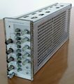
caption=Я4С-89 front panel | | caption=Я4С-89 front panel | | ||
series=[[Soviet 7000-series clones]]| | series=[[Soviet 7000-series clones]]| | ||
introduced= | | introduced=(?) | | ||
discontinued= | | discontinued=(?) | | ||
manuals= | |||
* ''please add'' [[Category:Manual needed]] | |||
}} | }} | ||
| Line 14: | Line 15: | ||
generator head. It can free-run or take a 5 V external trigger signal. | generator head. It can free-run or take a 5 V external trigger signal. | ||
The pulse outputs require an external pulse shaping cable in order to be useful. The cables contain a | The pulse outputs require an external pulse shaping cable in order to be useful. The cables contain a [[Russian tunnel diodes|1И308К 50 mA tunnel diode]]. | ||
From the top, the connectors are: | From the top, the connectors are: | ||
| Line 38: | Line 39: | ||
{{BeginSpecs}} | {{BeginSpecs}} | ||
{{Spec | Period | 10μs to approx | {{Spec | Period | 10μs to approx 15 ms, or external trigger }} | ||
{{Spec | Post-trigger delay | 0 to approx | {{Spec | Post-trigger delay | 0 to approx 400 ns }} | ||
{{Spec | Rise time | Depends on external pulse shaper }} | {{Spec | Rise time | Depends on external pulse shaper }} | ||
{{Spec | Pulse width | | {{Spec | Pulse width | 10 ns to 10 μs in two ranges}} | ||
{{Spec | Trigger output amplitude | | {{Spec | Trigger output amplitude | −5 V to +5 V into 1 MΩ, −1 V to +1 V into 50 Ω }} | ||
{{Spec | Pulse output amplitude | | {{Spec | Pulse output amplitude | 200 mV or 400 mV depending on pulse shaper }} | ||
{{EndSpecs}} | {{EndSpecs}} | ||
Revision as of 06:40, 4 May 2018
The Я4С-89 is a plug-in for Soviet 7000-series clones which contains a pulse generator. It is intended for use with the sampling plugins in a similar manner to the Tek S-52 pulse generator head. It can free-run or take a 5 V external trigger signal.
The pulse outputs require an external pulse shaping cable in order to be useful. The cables contain a 1И308К 50 mA tunnel diode.
From the top, the connectors are:
- external 5 V (TTL) trigger in
- sync output, variable level and polarity
- positive-going pulse output
- negative-going pulse output
The buttons are:
- manual trigger
- external trigger mode
- period 1/0.1/0.01 ms
- delay 25/50/100/200 ns (can be added by pressing multiple buttons)
- pulse width 0.01/0.2 μs
The rotary controls are:
- external trigger level
- period vernier
- sync output amplitude, negative-zero-positive
- delay vernier
- pulse width
then two screwdriver bias adjustments for the positive-going and negative-going pulse outputs.
The connectors are СР50-73 type, which are almost compatible with BNC connectors but the latch is a tight fit and the centre contact can be unreliable.
Key Specifications
| Period | 10μs to approx 15 ms, or external trigger |
|---|---|
| Post-trigger delay | 0 to approx 400 ns |
| Rise time | Depends on external pulse shaper |
| Pulse width | 10 ns to 10 μs in two ranges |
| Trigger output amplitude | −5 V to +5 V into 1 MΩ, −1 V to +1 V into 50 Ω |
| Pulse output amplitude | 200 mV or 400 mV depending on pulse shaper |
Links
Pictures
-
Front
-
Threequarter view
-
Pulse shaper cables schematic


