517: Difference between revisions
No edit summary |
No edit summary |
||
| Line 21: | Line 21: | ||
as follows: | as follows: | ||
* Gain Stage 1: single-ended, six sections, distributed, [[6AK5]] | * Gain Stage 1: single-ended, six sections, distributed, [[6AK5]] pentodes | ||
* Gain Stage 2: single-ended, six sections, distributed, [[6AK5]] | * Gain Stage 2: single-ended, six sections, distributed, [[6AK5]] pentodes | ||
* Gain Stage 3: single-ended, seven sections, distributed, [[6AK5]] | * Gain Stage 3: single-ended, seven sections, distributed, [[6AK5]] pentodes | ||
* Trig Pickoff: one common-cathode [[6CB6]] pentode | |||
* Signal Delay: 51 feet of RG63U 125-ohm coaxial cable | * Signal Delay: 51 feet of RG63U 125-ohm coaxial cable | ||
* Phase Splitter: single-ended in, differential out, three sections, distributed, [[6CB6]] | * Phase Splitter: single-ended in, differential out, three sections, distributed, [[6CB6]] pentode | ||
* Gain Stage 4: differential, six sections, distributed, [[6CB6]] | * Gain Stage 4: differential, six sections, distributed, [[6CB6]] pentodes | ||
* Gain Stage 5: differential, twelve sections, distributed, [[6CB6]] | * Gain Stage 5: differential, twelve sections, distributed, [[6CB6]] pentodes | ||
The 517 uses 24kV | There is a trigger amplifier in the 517 which can its input from | ||
an external source, or | |||
from the trigger pickoff in the vertical pre-amp, or | |||
from the internal rate generator circuit. | |||
The trigger amplifier circuit has | |||
five stages: | |||
* Phase Splitter: [[6J6]] dual-triode connected as a differential amplifier | |||
* Gain Stage 1: single-ended, three sections, distributed, [[6AK5]] pentodes | |||
* Gain Stage 2: single-ended, three sections, distributed, [[6AK5]] pentodes | |||
* Gain Stage 3: single-ended, common-cathode, [[6AG7]] pentode | |||
* Gain Stage 4: single-ended, common-cathode, [[6AG7]] pentode | |||
The 517 uses 24kV total acceleration voltage on the CRT. This is generated by the Type 420 High Voltage | |||
Power Supply subsystem in the 517. It uses a 1.8kHz oscillator to produce the high voltage, unlike | Power Supply subsystem in the 517. It uses a 1.8kHz oscillator to produce the high voltage, unlike | ||
other Tek scopes which use HV oscillators in the ultrasonic range. | other Tek scopes which use HV oscillators in the ultrasonic range. | ||
Revision as of 17:07, 18 June 2011
The Tektronix 517 is a 50MHz scope introduced in 1950 or 1951. The power supply is an external box, like the 507, 551 and 555. The 517 does not take plug-ins. There is also a 517A. The 517 closely resembles a scope that Tektronix developed under a contract for the US military during 1949 and 1950.
The external power supply and oscilloscope are connected by a removable cable with Jones plugs on both ends. Units with serial numbers 101-1739 use a 12-pin Jones connectors; after that it is a 16-pin Jones connector. The voltages on the 12-pin connector are:
- Pin 1: +750V, regulated
- Pin 2: +475V, regulated
- Pin 3: +350V, unregulated
- Pin 4: +225V, regulated
- Pin 5: +150V, regulated
- Pin 6: Ground
- Pin 7: -250V, regulated
- Pin 8: +180V, unregulated
The 517 makes extensive use of the distributed amplifier concept. The vertical signal path is as follows:
- Gain Stage 1: single-ended, six sections, distributed, 6AK5 pentodes
- Gain Stage 2: single-ended, six sections, distributed, 6AK5 pentodes
- Gain Stage 3: single-ended, seven sections, distributed, 6AK5 pentodes
- Trig Pickoff: one common-cathode 6CB6 pentode
- Signal Delay: 51 feet of RG63U 125-ohm coaxial cable
- Phase Splitter: single-ended in, differential out, three sections, distributed, 6CB6 pentode
- Gain Stage 4: differential, six sections, distributed, 6CB6 pentodes
- Gain Stage 5: differential, twelve sections, distributed, 6CB6 pentodes
There is a trigger amplifier in the 517 which can its input from an external source, or from the trigger pickoff in the vertical pre-amp, or from the internal rate generator circuit. The trigger amplifier circuit has five stages:
- Phase Splitter: 6J6 dual-triode connected as a differential amplifier
- Gain Stage 1: single-ended, three sections, distributed, 6AK5 pentodes
- Gain Stage 2: single-ended, three sections, distributed, 6AK5 pentodes
- Gain Stage 3: single-ended, common-cathode, 6AG7 pentode
- Gain Stage 4: single-ended, common-cathode, 6AG7 pentode
The 517 uses 24kV total acceleration voltage on the CRT. This is generated by the Type 420 High Voltage Power Supply subsystem in the 517. It uses a 1.8kHz oscillator to produce the high voltage, unlike other Tek scopes which use HV oscillators in the ultrasonic range.
- Final Report on Tektronix MILSPEC High Speed Scope
- Tektronix 517 Calibration Guide
- Early 517 Manual (PDF)
- Later Manual Covering the 517 and 517A (PDF)
-
front
-
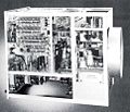
bottom internal
-
right internal
-
top internal
-
power supply internal
-
12-pin power connector


