531: Difference between revisions
No edit summary |
No edit summary |
||
| Line 11: | Line 11: | ||
* [http://w140.com/tek_fcp/tek_type_531_factory_cal_proc.pdf Tektronix 531 Factory Calibration Procedure (PDF)] | * [http://w140.com/tek_fcp/tek_type_531_factory_cal_proc.pdf Tektronix 531 Factory Calibration Procedure (PDF)] | ||
* [http://w140.com/tek_fcp/tek_type_531a_factory_cal_proc.pdf Tektronix 531A Factory Calibration Procedure (PDF)] | * [http://w140.com/tek_fcp/tek_type_531a_factory_cal_proc.pdf Tektronix 531A Factory Calibration Procedure (PDF)] | ||
* [[Media:070-301.pdf|Tektronix RM31A Manual (PDF)]] | |||
* [[Media:tek_531_fcp.pdf|Tektronix 531 Factory Calibration Procedure (PDF, OCR)]] | * [[Media:tek_531_fcp.pdf|Tektronix 531 Factory Calibration Procedure (PDF, OCR)]] | ||
* [[Media:tek_531a_fcp.pdf|Tektronix 531A Factory Calibration Procedure (PDF, OCR)]] | * [[Media:tek_531a_fcp.pdf|Tektronix 531A Factory Calibration Procedure (PDF, OCR)]] | ||
* [[Media:Tek 531a fcp feb 1968.pdf]] | * [[Media:Tek 531a fcp feb 1968.pdf|Tektronix 531A Factory Calibration Procedure, February 1968 (PDF)]] | ||
}} | }} | ||
Revision as of 03:15, 12 April 2020
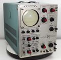
The Tektronix Type 531 is a 10 MHz oscilloscope that accepts letter-series and 1-series plug-ins.
It is exactly like Type 535 except it does not have the Delayed Sweep (dual timebase) feature.
The 531 and 535 were the first Tektronix scopes to accept plug-ins. It was introduced in March 1954 simultaneously with the Type 535, and superseded in 1959 by the Type 531A, which has more convenient controls and a slightly faster (15 MHz) vertical amplifier.
531s with below S/N 7950 have DuMont 5BGP2 instead of Tektronix T533P2.
In serial numbers 101 to 7600, the 531's L-C delay line is before the vertical amplifier. In serial numbers 7601 and up, the 531's delay line is between the vertical amplifier and the CRT. This change was the result of John Kobbe's insight that if the far end of the delay line was an open circuit (which the CRT approximates), the reflected wave could be absorbed at the source end. This "single termination" approach made it possible to do away with the output chassis. All Tek scopes using a lumped-constant delay line went to this topology.
There is also a rack-mount version, Types RM31 and RM31A. They have a sliding chassis so that the scope can be serviced without removing it from a rack.
The 532 is similar to the 531, but designed to be more reliable at the expense of slower risetime. The 541 is mostly the same as the 531, but has a distributed vertical amplifier for 30 MHz bandwidth, and a different CRT.
Key Specifications
| — 531 SN 101-7600 — | |
| Bandwidth | DC to 10 MHz (≤ 3 dB) with Type A plug-in |
| Rise time | 0.035 μs |
| — 531 SN 7601 up & 531A — | |
| Bandwidth | DC to 15 MHz (≤ 3 dB) with Type K plug-in |
| Rise time | 0.024 μs |
| — all — | |
| Line Voltage | 108/115/122/216/244 VAC ±10%,selected via primary voltage selector and voltage range selector switches, 50 Hz to 60 Hz. |
| Thermal Protection | Automatic resetting thermal cutout, in case internal temperature exceeds safe operating level |
| Power Consumption | 475W with plug-in |
| Cooling | AC Fan |
| Trigger Modes | AC/DC/AC LF Reject, and HF Sync |
| Anode Potential | 10 kV |
| Screen Area | 6 cm × 10 cm |
| Construction | Aluminum alloy chassis. Anodized front panel |
| Weight | 61,5 lbs / 27,8 kg |
Pictures of 531
Pictures of 531A
-
-
531A on 202 cart
-
531A Overwiev
-
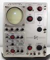
531A Front
-
531A Timebase ciruit
-
531A Power supply
-
531A Rectifier board
-
531A Inside left
-
531A Vertical amplifier
-
531A Inside right
-
manual compartment
Pictures of RM31A
-
RM31A


