067-0502-01: Difference between revisions
No edit summary |
No edit summary |
||
| Line 46: | Line 46: | ||
Tek 067-0502-01 front.jpg|067-0502-01 front | Tek 067-0502-01 front.jpg|067-0502-01 front | ||
067-0502-01-interior.jpg|067-0502-01 internal view | 067-0502-01-interior.jpg|067-0502-01 internal view | ||
067-0502-01-interior_det.jpg|067-0502-01 internal detail with V427 | 067-0502-01-interior_det.jpg|067-0502-01 internal detail with 6G11 as V427 | ||
</gallery> | </gallery> | ||
[[Category:Calibration fixtures]] | [[Category:Calibration fixtures]] | ||
[[Category:Pulse generators]] | [[Category:Pulse generators]] | ||
Revision as of 23:35, 22 September 2019

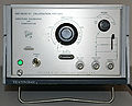
The Tektronix 067-0502-01Amplitude Calibrator and Comparator is an instrument that can be used to produce a reference rectangle voltage or current waveform and/or to compare an external unknown input with an internal or external reference.
The comparison is performed using an Airpax A175 chopper to switch between the two voltages that are being compared. The resulting output is a rectangular waveform with amplitude equal to the difference of two voltages. This waveform can be amplified and viewed on an oscilloscope.
The use of a chopper to make precise DC measurements is a well known and trusted technique, using instruments that are sensitive to AC, but not capable of drift-free DC performance.
The chopping technique can be used for calibration, comparing a device under test with a reference. In this case, the result of chopping is viewed on an oscilloscope oscilloscope, possibly with a preamplifier between the output of the chopper and the input of the oscilloscope.
The operator adjusts the device under test to minimize the amplitude observed on the oscilloscope. The vertical sensitivity, DC accuracy, and DC drift performance of the oscilloscope and preamplifier are not critical if the goal is simply to calibrate the device under test for optimal match with reference. However, if the objective of the calibration is to provide assurance that the error is less than some specific value, then the gain of the preamplifier and oscilloscope matters. Still, the gain of the preamp and oscilloscope only affect the accuracy of the tolerance, which is typically around 10%, (e.g., +/- 0.01% or +/- 0.3%).
See the 067-0502-00 page for a comparison of the -00 and -01 models.
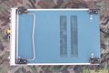
The HV supply uses a tube V427, to regulate the +300V supply. The manual lists V427 as a 7734, a triode-pentode, however some models contain a small circular adapter board (670-1860-00,388-2423-00) to adapt the noval tube socket to a Compactron socket and use a 6G11 double pentode instead. The adapter PCB connects the screen grid and plate of the beam power tube together in a triode configuration. These models also have 6G11 printed below V427 on the chassis.
Key Specifications
- please add
Manuals
Pictures
-
067-0502-01
-
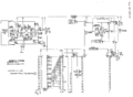
067-0502-01 Schematic
-

067-0502
-
067-0502-01 rear
-
067-0502-01 bottom
-
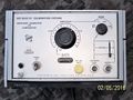
067-0502-01 front
-
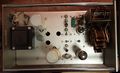
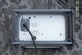
067-0502-01 internal view
-

067-0502-01 internal detail with 6G11 as V427


