S-42: Difference between revisions
No edit summary |
No edit summary |
||
| Line 1: | Line 1: | ||
{{Plugin Sidebar | {{Plugin Sidebar | ||
|manufacturer=Tektronix | |||
summary=Optical Sampling Head | | |series=7000 and 3S series sampling heads | ||
image=Tek s42.jpg | | |type=S-42 | ||
caption=S42 Head | |summary=Optical Sampling Head | ||
|image=Tek s42.jpg | |||
introduced=1989 | | |caption=S42 Head | ||
discontinued=1990 | | |introduced=1989 | ||
manuals= | |discontinued=1990 | ||
|designers= | |||
|manuals= | |||
* [[Media:S42.pdf | S-42 manual with schematics]] | * [[Media:S42.pdf | S-42 manual with schematics]] | ||
* [[Media:Tek s-42 specifics ordering information.pdf | S-42 Specifications Ordering Information]] | * [[Media:Tek s-42 specifics ordering information.pdf | S-42 Specifications Ordering Information]] | ||
}} | }} | ||
The '''Tektronix S-42''' is a sampling head for 1300 nm optical signals. It has an [[FC/PC connector|FC/PC fiberoptic connector]] | The '''Tektronix S-42''' is a sampling head for 1300 nm optical signals. It has an [[FC/PC connector|FC/PC fiberoptic connector]] for the input signal. It is essentially an [[S-4]] sampling head with a photodiode at the input. | ||
for the input signal. It is essentially an [[S-4]] sampling head with a photodiode at the input. | |||
Specified accuracy is for connections through 8/125 micron single-mode fibre, although | Specified accuracy is for connections through 8/125 micron single-mode fibre, although a lens in front of the photodiode allows connections using multi-mode fibre as well, at some degradation of response speed. | ||
a lens in front of the photodiode allows connections using multi-mode fibre as well, at some degradation | |||
of response speed. | |||
The manual shows it being used in a [[7S12]]-driven TDR setup with an external [[OT503|OT503 electro-optic converter]] as the optical signal source. | The manual shows it being used in a [[7S12]]-driven TDR setup with an external [[OT503|OT503 electro-optic converter]] as the optical signal source. | ||
| Line 34: | Line 33: | ||
The S-42 borrows heavily from the [[S-4]] sampling head, re-using the S-4 strobe, sampler and preamp boards. | The S-42 borrows heavily from the [[S-4]] sampling head, re-using the S-4 strobe, sampler and preamp boards. | ||
It uses the same six-diode traveling-wave sampling gate, strobed by 125 ps | It uses the same six-diode traveling-wave sampling gate, strobed by 125 ps pulses generated using a [[snap-off diode]] driven by an avalanche transistor. | ||
pulses generated using a [[snap-off diode]] driven by an avalanche transistor. | |||
The S-4's SMA input connector is still present internally, and driven electrically in some of the | The S-4's SMA input connector is still present internally, and driven electrically in some of the calibration procedures, with the photodiode removed. | ||
calibration procedures, with the photodiode removed. | |||
To accommodate the photo diode, the S-42's case is longer than the S-4's. When inserted, | To accommodate the photo diode, the S-42's case is longer than the S-4's. When inserted, the S-42 therefore protrudes from the base unit by about two centimeters. | ||
the S-42 therefore protrudes from the base unit by about two centimeters. | |||
==Pictures== | ==Pictures== | ||
Revision as of 07:57, 13 August 2021
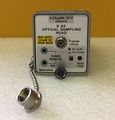
The Tektronix S-42 is a sampling head for 1300 nm optical signals. It has an FC/PC fiberoptic connector for the input signal. It is essentially an S-4 sampling head with a photodiode at the input.
Specified accuracy is for connections through 8/125 micron single-mode fibre, although a lens in front of the photodiode allows connections using multi-mode fibre as well, at some degradation of response speed.
The manual shows it being used in a 7S12-driven TDR setup with an external OT503 electro-optic converter as the optical signal source.
Key Specifications
| Pulse response | 55 ps |
|---|---|
| Bandwidth | 6.4 GHz (equiv.) |
| Spectral response | 1000 nm – 1700 nm |
| Deflection | 50 μW/Div to 50 mW/Div @ 1300 nm |
| Noise equivalent power | 42 μWRMS max. |
| Max. nondestructive input | 10 mW mean, 125 mW peak |
| Features |
|
Internals
The S-42 borrows heavily from the S-4 sampling head, re-using the S-4 strobe, sampler and preamp boards. It uses the same six-diode traveling-wave sampling gate, strobed by 125 ps pulses generated using a snap-off diode driven by an avalanche transistor.
The S-4's SMA input connector is still present internally, and driven electrically in some of the calibration procedures, with the photodiode removed.
To accommodate the photo diode, the S-42's case is longer than the S-4's. When inserted, the S-42 therefore protrudes from the base unit by about two centimeters.
Pictures
-
-
-
-
-
-
block diagram
-
schematic
-
S-42 spectral response
-
-
Description in 1989 Catalog
-


