107: Difference between revisions
Jump to navigation
Jump to search
No edit summary |
|||
| Line 1: | Line 1: | ||
{{Instrument Sidebar | |||
|manufacturer=Tektronix | |||
|model=107 | |||
|class=Signal Generator | |||
|series= | |||
|summary=squarewave generator | |||
|image=Tek_107_front1.jpg | |||
|caption=Tek 107 front | |||
|introduced=1958 | |||
|discontinued=(?) | |||
|designers= | |||
|manuals= | |||
* [https://w140.com/tek_107_clean.pdf Tektronix 107 Manual (PDF)] | |||
* [https://w140.com/tek_fcp/tek_type_107_field_cal_proc.pdf Tektronix 107 Factory Calibration Procedure (PDF)] | |||
}} | |||
The '''Tektronix 107 ''' is a squarewave generator [[introduced in 1958]]. | The '''Tektronix 107 ''' is a squarewave generator [[introduced in 1958]]. | ||
It is designed to provide a clean waveform with fast edges and flat tops for the calibration of oscilloscopes. | It is designed to provide a clean waveform with fast edges and flat tops for the calibration of oscilloscopes. | ||
| Line 10: | Line 25: | ||
{{Spec | Power | 100 W }} | {{Spec | Power | 100 W }} | ||
{{EndSpecs}} | {{EndSpecs}} | ||
==Internals== | ==Internals== | ||
| Line 45: | Line 55: | ||
[[Category:Pulse generators]] | [[Category:Pulse generators]] | ||
Revision as of 05:21, 18 August 2021
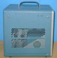
The Tektronix 107 is a squarewave generator introduced in 1958.
It is designed to provide a clean waveform with fast edges and flat tops for the calibration of oscilloscopes.
Key Specifications
| Output | rectangular waveform, 100−500 mVp-p (variable) into 50 Ω |
|---|---|
| Rise time | less than 3 ns (fixed) when terminated into 50 Ω |
| Repetition rate | 400 kHz to 1 MHz (variable, uncalibrated) |
| Weight | 5.9 kg (13 pounds) |
| Power | 100 W |
Internals
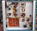
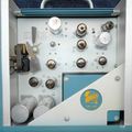
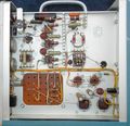
The signal path starts with an astable multivibrator composed of both halves of a 6BQ7A dual triode tube. The multivibrator circuit is cathode coupled to a pulse shaping circuit, and then to an output stage made from a single 6AU6 tube with a 50 Ω plate load, providing a controlled 50 Ω output impedance. The 50 Ω plate load keeps the voltage gain of output stage low, and the bandwidth high.
Pictures
-
-
-
-
-
-
Output, C94, R94, and R95
-
-
-
-
-
-
left external
-
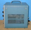
right external
-
Power on


