160: Difference between revisions
No edit summary |
|||
| Line 1: | Line 1: | ||
{{Oscilloscope Sidebar | |||
The '''Tektronix 160 series''' is a modular oscilloscope made from the mid-1950s | |manufacturer=Tektronix | ||
(schematics drawn in [[introduced in 1953|1953]]) to the late 1960s (in 1969 catalog). | |model=160 | ||
|series=160 | |||
|summary=Modular Oscilloscope | |||
|image=Tek_160a_360_161_162_trace.jpg | |||
|caption=160A 360 161 162 | |||
|introduced=1952 | |||
|discontinued=(?) | |||
|designers= | |||
|manuals= | |||
* [http://w140.com/tek_160.pdf Tektronix 160-series Manual (PDF)] | |||
* [http://w140.com/tek_360_160_irb.pdf Tektronix 160-series Instrument Reference Book (PDF, OCR)] | |||
* [[Media:Tek 160a fcp.pdf|Tektronix 160a Factory Calibration Procedure (PDF, OCR)]] | |||
}} | |||
The '''Tektronix 160 series''' is a modular oscilloscope made from the mid-1950s (schematics drawn in [[introduced in 1953|1953]]) to the late 1960s (in 1969 catalog). | |||
A 160 series system typically includes a Type 160 power supply, | A 160 series system typically includes a Type 160 power supply, a [[360|Type 360 indicator unit]], and one or more of the [[161]], [[162]], and [[163]] trigger and sweep modules. | ||
a [[360|Type 360 indicator unit]], and one or more of the | |||
[[161]], [[162]], and [[163]] trigger and sweep modules. | |||
There is also a single-unit power supply, the [[126]]. | There is also a single-unit power supply, the [[126]]. | ||
Each module is the size of a small shoe box. Power connections are made behind | Each module is the size of a small shoe box. Power connections are made behind the modules using [[W160|Type W160]] cables that have [[octal connector]]s. | ||
the modules using [[W160|Type W160]] cables that have [[octal connector]]s. | The power cables can be connected in a star topology (Type 160 in the center) or can be daisy-chained using the loop-through connection on the back of each module. | ||
The power cables can be connected in a star topology (Type 160 in the center) | |||
or can be daisy-chained using the loop-through connection on the back of each module. | |||
Signal connections are made on the front, typically with banana plugs. | Signal connections are made on the front, typically with banana plugs. | ||
In a typical setup, the input signal is fed through a splitter to the Y-input of the | In a typical setup, the input signal is fed through a splitter to the Y-input of the 360 and the trigger input of the 161. | ||
360 and the trigger input of the 161. The 161 generates a trigger pulse that controls a 162, | The 161 generates a trigger pulse that controls a 162, which generates the horizontal ramp for the sweep. | ||
which generates the horizontal ramp for the sweep. This ramp signal is sent to the 360 horizontal input. | This ramp signal is sent to the 360 horizontal input. | ||
The signals on the front panel of the 160-series modules are all single-ended. | The signals on the front panel of the 160-series modules are all single-ended. | ||
According to the May 1952 issue of Tek Talk (page 6), | According to the May 1952 issue of Tek Talk (page 6), the 160 Series entered limited production in April of 1952. | ||
the 160 Series entered limited production in April of 1952. | |||
{{BeginSpecs}} | {{BeginSpecs}} | ||
| Line 40: | Line 47: | ||
{{Spec | 6.3 V output | AC, unregulated, 20 A max }} | {{Spec | 6.3 V output | AC, unregulated, 20 A max }} | ||
{{EndSpecs}} | {{EndSpecs}} | ||
==Internals== | ==Internals== | ||
| Line 89: | Line 90: | ||
</gallery> | </gallery> | ||
[[Category:160 system]] | [[Category:160 system]] | ||
Revision as of 04:52, 10 August 2021

The Tektronix 160 series is a modular oscilloscope made from the mid-1950s (schematics drawn in 1953) to the late 1960s (in 1969 catalog).
A 160 series system typically includes a Type 160 power supply, a Type 360 indicator unit, and one or more of the 161, 162, and 163 trigger and sweep modules. There is also a single-unit power supply, the 126.
Each module is the size of a small shoe box. Power connections are made behind the modules using Type W160 cables that have octal connectors. The power cables can be connected in a star topology (Type 160 in the center) or can be daisy-chained using the loop-through connection on the back of each module.
Signal connections are made on the front, typically with banana plugs.
In a typical setup, the input signal is fed through a splitter to the Y-input of the 360 and the trigger input of the 161. The 161 generates a trigger pulse that controls a 162, which generates the horizontal ramp for the sweep. This ramp signal is sent to the 360 horizontal input.
The signals on the front panel of the 160-series modules are all single-ended.
According to the May 1952 issue of Tek Talk (page 6), the 160 Series entered limited production in April of 1952.
Key Specifications
| — Type 160 Power Supply — | |
| +300 V output | DC, unregulated, 170 mA max |
| +225 V output | DC, regulated, 125 mA max |
| +150 V output | DC, regulated, 5 mA max |
| −170 V output | DC, regulated, 125 mA max |
| 6.3 V output | AC, unregulated, 10 A max |
| — Type 160A Power Supply — | |
| +300 V output | DC, unregulated, 250 mA max |
| +225 V output | DC, regulated, 175 mA max |
| +150 V output | DC, regulated, 15 mA max |
| +70 V output | DC, unregulated max load? |
| −170 V output | DC, regulated, 125 mA max |
| 6.3 V output | AC, unregulated, 20 A max |
Internals
The 160, 161, 162, and 163 use the ceramic strip and silver solder construction style that is prevalent in other Tektronix equipment of the era, such as the 500-series scopes like the 545.
The Type 360 indicator unit contains the CRT HV power supply and the vertical amplifier and is constructed using a single-sided printed circuit board.
The 360 has a phase splitter to generate the differential drive for the horizontal deflection plates. The 360 uses a standard 3WP series 3-inch CRT. The cathode voltage is −1850 V. No post-deflection acceleration is used.
The 160 power supply was produced with serial numbers 101-619. For serial numbers 620 and up, it is slightly different and is called the 160A.
The 160 and 160A both use a 5V4 rectifier tube for the negative voltage and two 5V4 tubes in parallel for the positive voltage.
Both use 5651 87-volt reference tubes.
The 160 and 160A differ in their output regulator circuits. The 160 uses a 6AS7 dual-triode tube, one half to regulate the +225 V output and the other half to regulate the −170 V output. The 160A uses both halves of a 6080 dual-triode in parallel to regulate the +225 V output, and two parallel 12B4 triodes to regulate the −170 V output.
Pictures
-
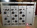
photo courtesy of Dave Nicol
-

photo courtesy of Dave Nicol
-

160 schematic
-

160A schematic
-
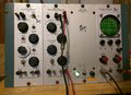
160 system in operation.
-

-

-

-

-

-

-

-


