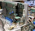
468: Difference between revisions
No edit summary |
No edit summary |
||
| Line 17: | Line 17: | ||
* [http://www.hakanh.com/dl/docs/kitinstructions/040-0999-02.pdf GPIB Option Installation] | * [http://www.hakanh.com/dl/docs/kitinstructions/040-0999-02.pdf GPIB Option Installation] | ||
{{ROM Images}} | |||
* [[Media:160-0459-01.bin |160-0459-01 (U565)]] | * [[Media:160-0459-01.bin |160-0459-01 (U565)]] | ||
* [[Media:160-0759-01.bin |160-0759-01 (U575)]] | * [[Media:160-0759-01.bin |160-0759-01 (U575)]] | ||
| Line 24: | Line 24: | ||
The '''Tektronix 468''' is a digital/analog scope, essentially a [[465B]] with an added 25 MS/s 8 bit digitizer. | The '''Tektronix 468''' is a digital/analog scope, essentially a [[465B]] with an added 25 MS/s 8 bit digitizer. | ||
{{BeginSpecs}} | |||
{{Spec | Bandwidth | 100 MHz analog, 10 MHz digital repetitive, 2.5 MHz digital single-shot }} | |||
{{Spec | Sampling rate | 25 MS/s }} | |||
* GPIB | {{Spec | Resolution | 8 bit }} | ||
* TV Sync Separator | {{Spec | Options | | ||
* | * Opt.02 − GPIB (A17 board) | ||
* Opt.05 − TV Sync Separator (A29 board) | |||
* ''please add | * Opt.11 − Analog X-Y/Plotter Output (A27 board) | ||
}} | |||
{{EndSpecs}} | |||
* ''please add'' ... [[Category:Specifications needed]] | |||
==Repair issues== | ==Repair issues== | ||
Revision as of 01:40, 2 January 2022
The Tektronix 468 is a digital/analog scope, essentially a 465B with an added 25 MS/s 8 bit digitizer.
Key Specifications
| Bandwidth | 100 MHz analog, 10 MHz digital repetitive, 2.5 MHz digital single-shot |
|---|---|
| Sampling rate | 25 MS/s |
| Resolution | 8 bit |
| Options |
|
- please add ...
Repair issues
Many 468s used Mostek MKB36000 masked ROMs that can suffer from "ROM rot". It may be necessary to replace the 160-0459-01 and 160-0759-01 ROMs with 2764 EPROMs through a 2364/2764 adapter. Another option might be using the MCM68766 EPROM.
-
replaced ROM by 2764 with homemade 2364/2764 adapter
-
Result of bad ROM by verification-check.
A16 STORAGE-DISPLAY Circuit Board Replacement ERROR in SERVICE Manual Schematic and Parts list (See Repairs)
Links
Pictures
-
-
-
front
-
top and A16
-
Storage & Display A16
-
right Trigger A12
-
left V Preamp A11
-
bottom Interface Board A15
-
rear
-
Processor Board Set
-
Microprocessor Board A21
-
Memory Board A18
-
Timebase/Power Supply A22
-
Timebase Oscillator A22


