5T1A: Difference between revisions
No edit summary |
(template, cat) |
||
| Line 1: | Line 1: | ||
The Tektronix 5T1A is a timing plug-in [[introduced in 1963]] for the [[661]] | {{Plugin Sidebar 2| | ||
[[sampling oscilloscope]]. | title=Tektronix 5T1A | | ||
summary=Timing plugin | | |||
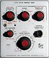
image=5t1a front.jpg | | |||
caption=5T1A front | | |||
series=[[661|661 Sampling Scope]] | | |||
introduced=1963 | | |||
discontinued=(?) | | |||
manuals= | |||
* [http://w140.com/kurt/tektronix_5t1a.pdf Tektronix 5T1A Manual (PDF)] | |||
* [http://w140.com/tek_fcp/tek_type_5t1a_factory_cal_proc.pdf Tektronix 5T1A Field Recalibration Procedure (PDF)] | |||
}} | |||
The '''Tektronix 5T1A''' is a timing plug-in [[introduced in 1963]] for the [[661]] | |||
[[sampling oscilloscope]]. | |||
It is an improved version of the [[5T1]]. The job of the 5T1A is to produce three signals: | It is an improved version of the [[5T1]]. The job of the 5T1A is to produce three signals: | ||
the sampling pulse, the horizontal sweep, and the blanking signal. | the sampling pulse, the horizontal sweep, and the blanking signal. | ||
| Line 7: | Line 20: | ||
* internally from the trigger pick-off in a [[4S1]] plug-in | * internally from the trigger pick-off in a [[4S1]] plug-in | ||
* externally via a GR-874 connector on the front panel of the 5T1A | * externally via a GR-874 connector on the front panel of the 5T1A | ||
* from the calibration oscillator in the 661, via the | * from the calibration oscillator in the 661, via the multi-pin plug-in connector | ||
* free-running | * free-running | ||
Each of these modes is suited to some measurement scenarios. | Each of these modes is suited to some measurement scenarios. | ||
| Line 14: | Line 27: | ||
through the 661, connecting the sampling unit to the timing unit. | through the 661, connecting the sampling unit to the timing unit. | ||
Triggering in the 5T1A is accomplished using five [[1N3129]] | Triggering in the 5T1A is accomplished using five [[1N3129]] 20 mA [[tunnel diodes]]. | ||
==Pictures== | |||
<gallery> | <gallery> | ||
File:5t1a front.jpg | |||
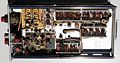
File:5t1a right.jpg | |||
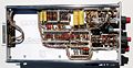
File:5t1a left.jpg | |||
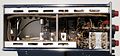
File:5t1a top.jpg | |||
File:5t1a bottom.jpg | |||
File:5t1a coax interconnect.jpg | |||
File:5t1a rear connector.jpg | |||
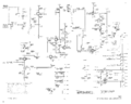
File:5t1a_trigger2.png|Trigger schematic | |||
File:5t1a fastramp.png|Fast Ramp schematic | File:5t1a fastramp.png|Fast Ramp schematic | ||
File:5t1a staircase gen.png|Staircase Generator schematic | File:5t1a staircase gen.png|Staircase Generator schematic | ||
Revision as of 12:09, 23 September 2014
Template:Plugin Sidebar 2 The Tektronix 5T1A is a timing plug-in introduced in 1963 for the 661 sampling oscilloscope.
It is an improved version of the 5T1. The job of the 5T1A is to produce three signals: the sampling pulse, the horizontal sweep, and the blanking signal. The input to the 5T1A is a trigger signal. The trigger can arrive from any of four sources:
- internally from the trigger pick-off in a 4S1 plug-in
- externally via a GR-874 connector on the front panel of the 5T1A
- from the calibration oscillator in the 661, via the multi-pin plug-in connector
- free-running
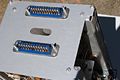
Each of these modes is suited to some measurement scenarios. In the case of internal triggering, the signal goes from the trigger pick-off in the 4S1 to a coaxial interconnect that passes through the 661, connecting the sampling unit to the timing unit.
Triggering in the 5T1A is accomplished using five 1N3129 20 mA tunnel diodes.
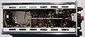
Pictures
-
-
-
-
-
-

-
-
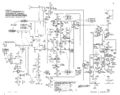
Trigger schematic
-
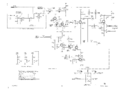
Fast Ramp schematic
-
Staircase Generator schematic


