7A19: Difference between revisions
(pics) |
(specs) |
||
| Line 4: | Line 4: | ||
image=7a19-front.jpg | | image=7a19-front.jpg | | ||
caption=7A19 front view| | caption=7A19 front view| | ||
years=? | | years=1971 — ? | | ||
type=Vertical Amplifier| | type=Vertical Amplifier| | ||
series=[[7000-series scopes]]| | series=[[7000-series scopes]]| | ||
| Line 15: | Line 15: | ||
An option (#4) was available that added a variable signal delay, intended to match timing between multiple channels. | An option (#4) was available that added a variable signal delay, intended to match timing between multiple channels. | ||
The pre-charge setting on the input coupling switch is intended for situations where there might be residual charge on the input coupling capacitor that could overload the input. To use it, one sets the switch to PRE-CHG before connecting the inout signal, then waits two seconds before switching to AC (LF point is 1 kHz). The PRE-CHG setting also serves as a ×100 attenuator having a 5 kΩ input impedance in series with 2 μF, extending LF cutoff down to 20 Hz. In the AC GND position, the input is disconnected from the amplifier and terminated in a capacitively coupled 50 Ω load. | |||
The 7A19 uses the [[155-0068-00]] amplifier IC. | The 7A19 uses the [[155-0068-00]] amplifier IC. | ||
==Specifications== | ==Specifications== | ||
{{BeginSpecs}} | |||
{{Spec | Input impedance | 50 Ω }} | |||
{{Spec | Bandwidth | 600 MHz (500 MHz in [[7904]]) }} | |||
{{Spec | Deflection | 10 mV/Div to 1 V/Div, 1—2—5 sequence. Pre-charge circuit may be used as a calibrated ×100 attenuator. }} | |||
{{Spec | Maximum input | 2 W average or 50 Div, in AC mode 100 V DC+peak AC }} | |||
{{Spec | Variable delay (Opt.4) | -0.5 ns to +0.5 ns}} | |||
{{EndSpecs}} | |||
==Pictures== | ==Pictures== | ||
| Line 50: | Line 57: | ||
[[Category:7000 series vertical plugins]] | [[Category:7000 series vertical plugins]] | ||
Revision as of 06:50, 14 August 2014
The 7A19 is a one-channel vertical plug-in for 7000-series scopes.
An option (#4) was available that added a variable signal delay, intended to match timing between multiple channels.
The pre-charge setting on the input coupling switch is intended for situations where there might be residual charge on the input coupling capacitor that could overload the input. To use it, one sets the switch to PRE-CHG before connecting the inout signal, then waits two seconds before switching to AC (LF point is 1 kHz). The PRE-CHG setting also serves as a ×100 attenuator having a 5 kΩ input impedance in series with 2 μF, extending LF cutoff down to 20 Hz. In the AC GND position, the input is disconnected from the amplifier and terminated in a capacitively coupled 50 Ω load.
The 7A19 uses the 155-0068-00 amplifier IC.
Specifications
Key Specifications
| Input impedance | 50 Ω |
|---|---|
| Bandwidth | 600 MHz (500 MHz in 7904) |
| Deflection | 10 mV/Div to 1 V/Div, 1—2—5 sequence. Pre-charge circuit may be used as a calibrated ×100 attenuator. |
| Maximum input | 2 W average or 50 Div, in AC mode 100 V DC+peak AC |
| Variable delay (Opt.4) | -0.5 ns to +0.5 ns |
Pictures
-
7A19 without option
-
7A19 with Opt. 4 (Variable Delay).
Earlier model
-
Left side (early model with Weinschel attenuator)
-
Right side (early model with Weinschel attenuator)
Later model (B030000+)
-
Left side
-
Right side
-
Front right, Tek-built attenuator
-
Rear right
-
Front left
-
Front right
-
Top view
-
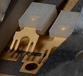
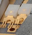
Attenuator switch contacts
-
Contacts detail
-
Contacts detail


