7A19

The Tektronix 7A19 is a one-channel 600 MHz vertical amplifier plug-in for 7000-series scopes, designed by Thor Hallen and Val Garuts and was introduced along with the 7904 mainframe in late 1971/early 1972 (note 1).
Key Specifications
| Bandwidth | 600 MHz (500 MHz in 7904) |
|---|---|
| Deflection | 10 mV/Div to 1 V/Div, 1−2−5. Pre-charge circuit may be used as a calibrated ×100 attenuator. |
| Maximum input | 2 W average or 50 Div, in AC mode 100 V DC+peak AC |
| Input impedance | 50 Ω |
| Variable delay (Opt.4) | −0.5 ns to +0.5 ns |
Operation
The 7A19 has no variable gain control. An option (#4) was available that added a variable signal delay (±0.5 ns implemented using a mechanically variable passive delay line), intended to match timing between multiple channels.
The pre-charge setting on the input coupling switch is intended for situations where there might be residual charge on the input coupling capacitor that could overload the input. To use it, one sets the switch to PRE-CHG before connecting the input signal, then waits two seconds before switching to AC (LF point is 1 kHz). The PRE-CHG setting also serves as a ×100 attenuator having a 5 kΩ input impedance in series with 2 μF, extending LF cutoff down to 20 Hz. In the AC GND position, the input is disconnected from the amplifier and terminated in a capacitively coupled 50 Ω load.
Links
Patents that may apply to 7A19
| Page | Title | Inventors | Filing date | Grant date | Links |
|---|---|---|---|---|---|
| Patent US 3562464A | Cam actuated switch having movable and fixed contacts on circuit board | Howard Vollum • Willem H Verhoef • Tony Sprando | 1968-10-07 | 1971-02-09 | Cam switches • 1501 • 2101 • 2701 • 2703 • 432 • 434 • 465 • 475 • 5A15N • 5A18N • 5A20N • 5A21N • 5A38 • 5A45 • 5B10N • 5B12N • 7A15 • 7A16A • 7A18 • 7A19 • 7A24 • 7A26 • 7B10 • 7B15 • 7B50 • 7B51 • 7B52 • 7B53A • 7B50A • 7B70 • 7B71 • 7B80 • 7B85 • 7B87 • 7B92 • 7B92A • 7D01 • 7D12 • 7D15 • 7J20 • 7S12 • 7T11 • 7T11A • AF501 • AM502 • AM503 • DC502 • DC503 • DC504 • DC505 • DM501 • DM502 • FG501 • FG501A • FG502 • FG503 • FG504 • FG507 • PG501 • PG502 • PG505 • PG506 • PG506A • PG508 • TG501 • SC502 • SC503 • SC504 |
| Patent US 3719788A | Switch having ganged contacts mounted on opposite sides of circuit board | Ken Holland • Tony Sprando | 1971-02-04 | 1973-03-06 | 465 • 475 • 5A38 • 5A45 • 7A15 • 7A16A • 7A18 • 7A19 • 7A24 • 7A26 • 7D15 • PG506 |
| Patent US 3753170A | Step attenuator apparatus having attenuator stages selectively connected in cascade by cam actuated switches | Ken Holland | 1971-02-10 | 1973-08-14 | 465 • 475 • 5A38 • 5A45 • 7A15 • 7A16A • 7A18 • 7A19 • 7A24 • 7A26 |
| Patent US 3875542A | High frequency fuse | Ken Holland • John Alan Roberts | 1973-09-10 | 1975-04-01 | 7A19 • 7A24 |
| Patent US 3900711A | Electrical contactor assembly for high frequency applications | Ken Holland | 1974-02-04 | 1975-08-19 | 465 • 475 • 5A38 • 5A45 • 7A15 • 7A16A • 7A18 • 7A19 • 7A24 • 7A26 • 7D15 • AM503 |
Internals
The 50 Ω input impedance of the 7A19 is provided by a pair of 100 Ω resistors in parallel. The resistors are protected by a pair of fuses in parallel. The manual explains that the motivation for using two fuses in parallel is to minimize the effect of the series impedance of the fuses. The fuse part number in the manual (Littelfuse 279-100) appears to be wrong since the MICRO 279 series fuse has 25.4 mm long pins. The correct replacement fuse is Littelfuse 273-100 which comes in a box of 5 labeled "MICRO 1/10A 273", it has 4.32 mm long pins.
The only active device in the vertical signal path of the 7A19 is an 155-0068-00 amplifier hybrid, (U40, Tek internal part number H101). A second 155-0068-00 is used in the trigger signal path of the 7A19, which is almost identical to the vertical signal path.
The 7A19 uses the ±50 V supplies provided by the mainframe.
Notes
- See 7A11 and John Addis, Good Engineering and Fast Vertical Amplifiers, in Jim Williams (Ed.), Analog Circuit Design: Art, Science and Personalities (1991), p. 114, and Tektronix New Products 1972.
Prices
| Year | 1972 | 1977 | 1980 | 1984 | 1987 | 1990 |
|---|---|---|---|---|---|---|
| Catalog price | $500 | $1,000 | $1,475 | $2,450 | $2,895 | $3,340 |
| In 2023 Dollars | $3,700 | $5,100 | $5,500 | $7,300 | $7,900 | $7,900 |
Pictures
-
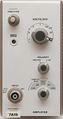
7A19 without option
-
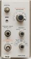
7A19 with Opt. 4 (Variable Delay).

Earlier model
-
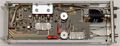
Left side (early model with Weinschel attenuator, without Opt. 4)
-

Right side (early model with Weinschel attenuator)


Later model (B030000+)
-
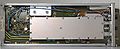
Left side (Opt.4 delay line enclosure in front)
-
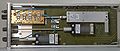
Right side
-
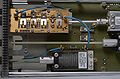
Front right, Tek-built attenuator
-
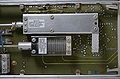
Rear right
-
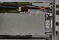
Front left
-
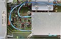
Front right
-
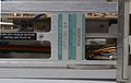
Top view
-
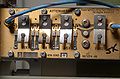
Attenuator switch contacts
-
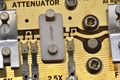
Attenuator element
-
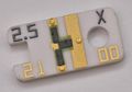
Attenuator element
-
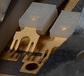
Contacts detail
-
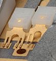
Contacts detail
-
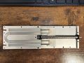
Internals of mechanical delay system of 7A19 (opt 4)
-
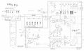
Late-model 7A19 schematic


Components
Some Parts Used in the 7A19
| Part | Part Number(s) | Class | Description | Used in |
|---|---|---|---|---|
| 155-0068-00 | 155-0068-00 | Hybrid integrated circuit | amplifier | 7A19 |