512: Difference between revisions
No edit summary |
(template, cat) |
||
| Line 1: | Line 1: | ||
The Tektronix Type 512 is a | {{Oscilloscope Sidebar | | ||
title=Tektronix 512| | |||
summary=2 MHz scope | | |||
image=Tek 512 front.jpg | | |||
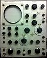
caption=Tek 512 | | |||
introduced=1948 | | |||
discontinued=(?) | | |||
manuals= | |||
* [http://w140.com/tek_512_early.pdf Tektronix 512 Manual (early, PDF)] | |||
* [http://w140.com/tek_512.pdf Tektronix 512 Manual (late, PDF)] | |||
}} | |||
The '''Tektronix Type 512''' is a 2 MHz oscilloscope [[introduced in 1948]]. | |||
Tektronix engineer Logan Belleville did most of the | Tektronix engineer Logan Belleville did most of the | ||
design work for the 512. The maximum sensitivity is | design work for the 512. The maximum sensitivity is 5 mV/cm. The vertical signal path, fully differential and DC coupled from the front panel A and B inputs to the vertical deflection plates, is as follows: | ||
fully differential and DC coupled from the front panel A and B inputs to the vertical deflection plates, | |||
is as follows: | |||
* Stage 1: differential, [[5879]] pentodes | * Stage 1: differential, [[5879]] pentodes | ||
| Line 19: | Line 28: | ||
Built-in true differential inputs are also seen in later scopes such as the [[502]], [[503]], and [[504]]. | Built-in true differential inputs are also seen in later scopes such as the [[502]], [[503]], and [[504]]. | ||
The input impedance is | The input impedance is 1 MΩ in parallel with 45 pF. The 512 uses a total of 3 kV of acceleration voltage: -1500 V for the cathode, +1500 V for the anode. It weighs 54 pounds and uses 280 watts. It has no [[thermal cutoff]]. | ||
voltage: - | |||
Up to serial number 2525, the 512 used the [[5CPA]] CRT. After that, the [[5ABP]] CRT was used. | Up to serial number 2525, the 512 used the [[5CPA]] CRT. After that, the [[5ABP]] CRT was used. | ||
| Line 44: | Line 53: | ||
Tektronix 512 oscilloscopes with serial numbers 101 through 2146 | Tektronix 512 oscilloscopes with serial numbers 101 through 2146 | ||
have an unregulated HV power supply that uses a | have an unregulated HV power supply that uses a 2 kHz oscillation frequency and | ||
has no regulation. Starting at serial number 2147, the HV power | has no regulation. Starting at serial number 2147, the HV power | ||
supply runs at | supply runs at 70 kHz and has regulation in form that is typical | ||
of Tek scopes of the 1950's and 1960's. | of Tek scopes of the 1950's and 1960's. | ||
The CRT cathode voltage is compared with the - | The CRT cathode voltage is compared with the -150 V supply and | ||
an error signal is produced, which controls the screen voltage on | an error signal is produced, which controls the screen voltage on | ||
the HV oscillator pentode. | the HV oscillator pentode. | ||
| Line 61: | Line 70: | ||
the blanking signal from the sweep circuit to control the DC voltage | the blanking signal from the sweep circuit to control the DC voltage | ||
of the "grounded" end of the secondary that produces the CRT grid voltage. | of the "grounded" end of the secondary that produces the CRT grid voltage. | ||
When the grounded end is shifted up and down by | When the grounded end is shifted up and down by 50 V, the CRT grid voltage | ||
is shifted up and down by | is shifted up and down by 50 V relative to the constant cathode voltage, | ||
thereby controlling CRT beam current. | thereby controlling CRT beam current. | ||
| Line 72: | Line 81: | ||
taken in the 512 was to modulate the blanking signal on a carrier, | taken in the 512 was to modulate the blanking signal on a carrier, | ||
much like a CW transmitter sending morse code (or any other on-off signal). | much like a CW transmitter sending morse code (or any other on-off signal). | ||
The signal passes through a transformer which has approximately | The signal passes through a transformer which has approximately 0 V<sub>DC</sub> | ||
on the primary side and approximately -1500VDC on the secondary side. | on the primary side and approximately -1500VDC on the secondary side. | ||
The signal from the secondary is demodulated, recovering the blanking signal, | The signal from the secondary is demodulated, recovering the blanking signal, | ||
which controls the grid voltage on the CRT. | which controls the grid voltage on the CRT. | ||
==Pictures== | |||
<gallery> | <gallery> | ||
Image:Tek 512 front.jpg | Image:Tek 512 front.jpg | ||
| Line 85: | Line 92: | ||
Image:Tek 512 bottom rear.jpg|Bottom rear | Image:Tek 512 bottom rear.jpg|Bottom rear | ||
</gallery> | </gallery> | ||
[[Category:Tube scopes]] | |||
Revision as of 11:14, 21 August 2014

The Tektronix Type 512 is a 2 MHz oscilloscope introduced in 1948. Tektronix engineer Logan Belleville did most of the design work for the 512. The maximum sensitivity is 5 mV/cm. The vertical signal path, fully differential and DC coupled from the front panel A and B inputs to the vertical deflection plates, is as follows:
- Stage 1: differential, 5879 pentodes
- Stage 2: differential, 12AU6 pentodes
- Stage 3: differential, 12AU6 pentodes
- Stage 4: differential, 12AU6 pentodes
- Stage 5: differential, 6AG7 pentodes
Frequency response extending all the way down to DC was a distinguishing feature at the time the 512 introduced.
The 512 has two inputs, "A" and "B", each having its own UHF connector. The scope can be used with a single input or it can used in "A-B" mode, where the displayed signal is the difference between the voltage at the A input and the voltage at the B input. Built-in true differential inputs are also seen in later scopes such as the 502, 503, and 504.
The input impedance is 1 MΩ in parallel with 45 pF. The 512 uses a total of 3 kV of acceleration voltage: -1500 V for the cathode, +1500 V for the anode. It weighs 54 pounds and uses 280 watts. It has no thermal cutoff.
Up to serial number 2525, the 512 used the 5CPA CRT. After that, the 5ABP CRT was used.
The Tektronix 512 normally came with P7 phosphor. P1 and P11 were optional, at no charge. Options were also available for different ranges of sweep rates.
The Tek 512 manual says,
Since 1954, we have manufactured our own timing capacitors with the characteristics needed to maintain sweep-time accuracy and linearity. The capacitance ratio between the capacitors used is accurate within half of one per cent so that the time-base calibrations will be right at all speeds. Most capacitors change value with voltage, temperature, and age. Variation of capacitance with voltage is particularly undesirable because it causes nonlinearity of the time-base sawtooth. Our timing capacitors are especially free from this voltage effect. They also have minimum temperature and aging variations.
Tektronix 512 oscilloscopes with serial numbers 101 through 2146 have an unregulated HV power supply that uses a 2 kHz oscillation frequency and has no regulation. Starting at serial number 2147, the HV power supply runs at 70 kHz and has regulation in form that is typical of Tek scopes of the 1950's and 1960's. The CRT cathode voltage is compared with the -150 V supply and an error signal is produced, which controls the screen voltage on the HV oscillator pentode.
In both the regulated and unregulated versions of the Tek 512 HV supply, the CRT cathode and anode voltages are produced by half-wave rectification of a single secondary on the HV transformer. Later Tek scopes (e.g., the 531, have two secondaries on the HV transformer. One secondary produces the CRT grid voltage and the other secondary produces the CRT cathode and anode voltages. The later design allows the the blanking signal from the sweep circuit to control the DC voltage of the "grounded" end of the secondary that produces the CRT grid voltage. When the grounded end is shifted up and down by 50 V, the CRT grid voltage is shifted up and down by 50 V relative to the constant cathode voltage, thereby controlling CRT beam current.
The blanking circuit in the 512 is somewhat unusual. Since the 512 is designed to work all the way down to DC and support slow sweeps with long waiting time between trigger events, the blanking circuit needs to be able to keep the beam on or off for unlimited time, which precludes simple AC-coupled blanking. The approach taken in the 512 was to modulate the blanking signal on a carrier, much like a CW transmitter sending morse code (or any other on-off signal). The signal passes through a transformer which has approximately 0 VDC on the primary side and approximately -1500VDC on the secondary side. The signal from the secondary is demodulated, recovering the blanking signal, which controls the grid voltage on the CRT.
Pictures
-
-
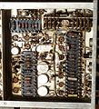
Bottom front
-
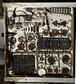
Bottom rear

