1240: Difference between revisions
No edit summary |
No edit summary |
||
| Line 12: | Line 12: | ||
}} | }} | ||
The '''Tektronix 1240''' is a logic analyzer. The | The '''Tektronix 1240''' is a logic analyzer. The '''1241''' is the same device but with a color-shutter CRT. | ||
==Specifications== | ==Specifications== | ||
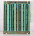
The 1240/1241 | The 1240/1241 accommodate one to four acquisition boards of type '''1240D1''' with 9 channels or '''1240D2''' with 18 channels | ||
for a total of up to 72 acquisition channels. Acquisition speeds reach up to 100 MHz asynchronous or 50 MHz synchronous. | |||
The 1240/41 provides 14 levels of triggering with conditional branching. | |||
Exchangeable ROM cartridges allow for mnemonic disassembly and state analysis of most microprocessors of the time. | Exchangeable ROM cartridges allow for mnemonic disassembly and state analysis of most microprocessors of the time. | ||
An optional "Comm Pack" provides a serial port including remote control capabilities. | |||
==Internals== | ==Internals== | ||
| Line 27: | Line 31: | ||
==Links== | ==Links== | ||
* [http://www.barrytech.com/tektronix/logic_analyzers/tek1240.html Tektronix 1240] / [http://www.barrytech.com/tektronix/logic_analyzers/tek1241.html 1241] @ barrytech.com | * [http://www.barrytech.com/tektronix/logic_analyzers/tek1240.html Tektronix 1240] / [http://www.barrytech.com/tektronix/logic_analyzers/tek1241.html 1241] / [http://www.barrytech.com/tektronix/logic_analyzers/tek1240_d2.html 120D2] @ barrytech.com | ||
== Pictures == | == Pictures == | ||
| Line 33: | Line 37: | ||
<gallery> | <gallery> | ||
Tektronix_1240_front_panel.jpeg | Tektronix 1240, front view | Tektronix_1240_front_panel.jpeg | Tektronix 1240, front view | ||
Tektronix_1240_rear_panel.jpeg | Rear panel (note second power switch) | Tektronix_1240_rear_panel.jpeg | Rear panel (note second power switch) | ||
Tek 1241 front.jpg | Tektronix 1241, front view | |||
Tek 1241 rear.jpg | Tektronix 1241, rear view | |||
Tektronix_1240_probe_panel.jpeg | Side with probe panel | Tektronix_1240_probe_panel.jpeg | Side with probe panel | ||
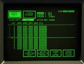
Tek 1240 selftest.jpg| 1240 self test display | |||
Tek 1240 state view.jpg| 1240 state table view | |||
Tek 1240 timing diagram view.jpg| 1240 timing diagram view | |||
Tek 155-0270-00 from 1240.jpg | Tek [[155-0270-00]] probe data interface hybrid (one of three) | Tek 155-0270-00 from 1240.jpg | Tek [[155-0270-00]] probe data interface hybrid (one of three) | ||
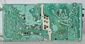
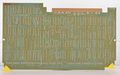
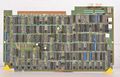
Tek 1240 A06 CRT Drive.jpg | A06 CRT drive board (also includes comms pack interface) | Tek 1240 A06 CRT Drive.jpg | A06 CRT drive board (also includes comms pack interface) | ||
Revision as of 08:21, 1 July 2017

The Tektronix 1240 is a logic analyzer. The 1241 is the same device but with a color-shutter CRT.
Specifications
The 1240/1241 accommodate one to four acquisition boards of type 1240D1 with 9 channels or 1240D2 with 18 channels for a total of up to 72 acquisition channels. Acquisition speeds reach up to 100 MHz asynchronous or 50 MHz synchronous. The 1240/41 provides 14 levels of triggering with conditional branching.
Exchangeable ROM cartridges allow for mnemonic disassembly and state analysis of most microprocessors of the time.
An optional "Comm Pack" provides a serial port including remote control capabilities.
Internals
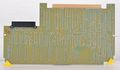
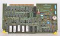
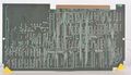
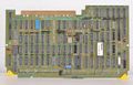
The 1240 is built around an Intel 8088 as the control processor with 64K DRAM, and firmware in a bank of EPROMs. A separate I/O processor board is powered by a Z80A CPU. The display controller is built from individual TTL and ECL ICs.
The power supply is a switch-mode supply that mainly generates 5 V at up to 45 A. It requires a minimum load of 11.6 A. Additionally it generates 3 V at up to 8 A with no minimum load and several other voltages that are derived from linear post regulators.
Boards are two to six layers.
Links
- Tektronix 1240 / 1241 / 120D2 @ barrytech.com
Pictures
-
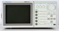
Tektronix 1240, front view
-
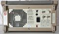
Rear panel (note second power switch)
-
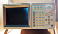
Tektronix 1241, front view
-

Tektronix 1241, rear view
-

Side with probe panel
-
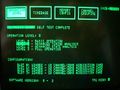
1240 self test display
-
1240 state table view
-
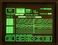
1240 timing diagram view
-
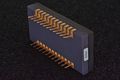
Tek 155-0270-00 probe data interface hybrid (one of three)
-

A06 CRT drive board (also includes comms pack interface)
-

A06 CRT drive board (rear side)
-
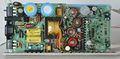
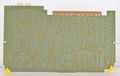
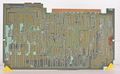
A07 Power supply
-
A07 Power supply (rear side)
-
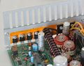
A07 Power supply low voltage regulators
-
A08 Interface board
-
A08 Interface board (rear side)
-

A09 Control processor board
-
A09 Control processor board (rear side)
-
A10 I/O processor board
-
A10 I/O processor board (rear side)
-
A11 Display generator board
-
A11 Display generator board (rear side)
-
A14 Trigger board
-
A14 Trigger board (rear side)
-

A15 9 channel board
-
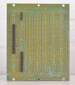
A15 9 channel board (rear side)


