524: Difference between revisions
No edit summary |
No edit summary |
||
| Line 9: | Line 9: | ||
* [http://bama.edebris.com/download/tek/524ad/Tek%20524AD.pdf Tektronix 524AD Manual (PDF)] | * [http://bama.edebris.com/download/tek/524ad/Tek%20524AD.pdf Tektronix 524AD Manual (PDF)] | ||
}} | }} | ||
The '''Tektronix 524''' is | The '''Tektronix 524''' is a monolithic oscilloscope [[introduced in 1953]] for monitoring television waveforms, designed by [[Cliff Moulton]]. | ||
Interestingly, the 524 appears on page 33 of the [http://www.americanradiohistory.com/Archive-Catalogs/RCA-Test-Equip-1966.pdf 1966 RCA Test Equipment Catalog]. | Interestingly, the 524 appears on page 33 of the [http://www.americanradiohistory.com/Archive-Catalogs/RCA-Test-Equip-1966.pdf 1966 RCA Test Equipment Catalog]. | ||
| Line 17: | Line 17: | ||
The 524 weighs 61 pounds, uses 500 watts, and has a [[thermal cutoff]]. It uses [[selenium rectifiers]] in the low-voltage | The 524 weighs 61 pounds, uses 500 watts, and has a [[thermal cutoff]]. It uses [[selenium rectifiers]] in the low-voltage | ||
power supply. It has a total of 4 kV CRT beam acceleration, | power supply. It has a total of 4 kV CRT beam acceleration, | ||
−1.5 kV on the cathode and +2.5 kV on the anode. | |||
It normally came with a [[5ABP1]] CRT which has P1 [[phosphor]], | It normally came with a [[5ABP1]] CRT which has P1 [[phosphor]], | ||
but P7 and P11 phosphors were also available. | but P7 and P11 phosphors were also available. | ||
| Line 39: | Line 39: | ||
conventional trigger circuit and sweep circuit similar to that of the 514. | conventional trigger circuit and sweep circuit similar to that of the 514. | ||
The 524 uses a cylindrical style of ceramic terminal strip, | The 524 uses a cylindrical style of ceramic terminal strip, which is less common than the straight style. | ||
which is less common than the straight style. | |||
The cylindrical style is also used in the [[C|Type C]], [[CA|Type CA]], and [[315]]. | The cylindrical style is also used in the [[C|Type C]], [[CA|Type CA]], and [[315]]. | ||
| Line 47: | Line 46: | ||
==Pictures== | ==Pictures== | ||
<gallery> | <gallery> | ||
Tek 524 trace.jpg|Displaying a squarewave | |||
Tek 524ad front fl.jpg | |||
Tek 524ad front.jpg | |||
Tek 524 marker switch.jpg|Marker switch | |||
Tek 524 round terminal strip.jpg|Unusual round terminal strips in the 524 | |||
Tek 524 internal.jpg|Top right internal view | |||
Tek 524 selenium rectifier.jpg|Selenium rectifier and unusual fan mount | |||
Image:TimeMarkGenFor524.jpg|Time Mark Gen for 524 | Image:TimeMarkGenFor524.jpg|Time Mark Gen for 524 | ||
Tek 524 syncsep.png|Sync Separator | |||
Tek 524 bottom front2.jpg|Bottom front, power supply circuitry | |||
Tek 524 bottom rear2.jpg|Bottom rear, transformer wiring | |||
Tek 524ad cl1.jpg | Tek 524ad cl1.jpg | ||
Tek 524ad cl2.jpg | Tek 524ad cl2.jpg | ||
Tek 524ad cl3.jpg | Tek 524ad cl3.jpg | ||
524AD-cartoon-1960.jpg | [[Cartoons|Cartoon]] in 1960 version of circuit diagrams | |||
</gallery> | |||
===Early model=== | |||
<gallery> | |||
Tek early 524ad 1.jpg | |||
Tek early 524ad 2.jpg | |||
Tek early 524ad 3.jpg | |||
Tek early 524ad 4.jpg | |||
Tek early 524ad 5.jpg | |||
Tek early 524ad 6.jpg | |||
Tek early 524ad 7.jpg | |||
Tek early 524ad 8.jpg | |||
Tek early 524ad 9.jpg | |||
</gallery> | </gallery> | ||
[[Category:Monolithic tube scopes]] | [[Category:Monolithic tube scopes]] | ||
Revision as of 01:32, 6 August 2018
The Tektronix 524 is a monolithic oscilloscope introduced in 1953 for monitoring television waveforms, designed by Cliff Moulton.
Interestingly, the 524 appears on page 33 of the 1966 RCA Test Equipment Catalog.
Key Specifications
- please add
The 524 weighs 61 pounds, uses 500 watts, and has a thermal cutoff. It uses selenium rectifiers in the low-voltage power supply. It has a total of 4 kV CRT beam acceleration, −1.5 kV on the cathode and +2.5 kV on the anode. It normally came with a 5ABP1 CRT which has P1 phosphor, but P7 and P11 phosphors were also available.
Internals
The vertical signal path of the 524 is similar to that of the 514. They have similar front-ends and similar distributed vertical output amplifiers.
The video trigger circuitry present in the 524 distinguish it from the 514. Just before the L-C delay line in the vertical signal path, there is a cathode follower, V15A, that serves as the trigger pickoff buffer. The resulting trigger signal goes to a video sync separator circuit. Here, the there is clamping and amplification and, most importantly, a non-retriggerable multivibrator. The multivibrator is triggered by the vertical sync of the NTSC waveform. After being triggered, it is not triggerable again for about about 25 ms, so it misses the vertical sync of the next interlaced field and instead triggers on the vertical sync of one following that. So it consistently shows the "even" field or the "odd" field. There is a switch that perturbs the multivibrator so it can be switched between even and odd fields. The video trigger circuit drives a conventional trigger circuit and sweep circuit similar to that of the 514.
The 524 uses a cylindrical style of ceramic terminal strip, which is less common than the straight style. The cylindrical style is also used in the Type C, Type CA, and 315.
Pictures
-
Displaying a squarewave
-
-
-
Marker switch
-
Unusual round terminal strips in the 524
-
Top right internal view
-
Selenium rectifier and unusual fan mount
-
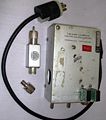
Time Mark Gen for 524
-
Sync Separator
-
Bottom front, power supply circuitry
-
Bottom rear, transformer wiring
-
-
-
-
Cartoon in 1960 version of circuit diagrams


