155-0076-00: Difference between revisions
| Line 21: | Line 21: | ||
[[File:Tek m94 probe ring decoder.png|600px|M94 Probe Ring Decoder]] | [[File:Tek m94 probe ring decoder.png|600px|M94 Probe Ring Decoder]] | ||
---- | |||
When a 10x probe is connected, the voltage of the probe pin ring is determined by a voltage divider | When a 10x probe is connected, the voltage of the probe pin ring is determined by a voltage divider | ||
formed by the 5 kΩ resistor (to +5 V) in the scope and the 11 kΩ resistor (to ground) in the probe. | formed by the 5 kΩ resistor (to +5 V) in the scope and the 11 kΩ resistor (to ground) in the probe. | ||
| Line 31: | Line 31: | ||
[[File:Tek m94 probe ring decoder 11k.png|600px]] | [[File:Tek m94 probe ring decoder 11k.png|600px]] | ||
---- | |||
When a 100x probe is connected, the voltage at pin 11 is 2.77 V. | When a 100x probe is connected, the voltage at pin 11 is 2.77 V. | ||
Q57 is on and Q56 is off. | Q57 is on and Q56 is off. | ||
| Line 40: | Line 40: | ||
[[File:Tek m94 probe ring decoder 6.2k.png|600px]] | [[File:Tek m94 probe ring decoder 6.2k.png|600px]] | ||
---- | |||
Some probes have an "identify" button. | Some probes have an "identify" button. | ||
When pressed, that button shorts the probe detect pin to ground. | When pressed, that button shorts the probe detect pin to ground. | ||
| Line 50: | Line 50: | ||
[[File:Tek m94 probe ring decoder identify.png|600px]] | [[File:Tek m94 probe ring decoder identify.png|600px]] | ||
---- | |||
==Used in== | ==Used in== | ||
Revision as of 12:10, 24 December 2018
The Tektronix 155-0076-00 (M94) is a Tek-made input protection and probe logic integrated circuit in a 16-pin minipac package, designed by John Addis.
Probe Readout Ring Decoder
The M94 has a circuit for decoding the probe attenuation factor based on the probe readout pin. The probe readout pin contacts the readout ring on the probe input of the scope. The readout ring is pulled up to 5 volts by a 5 kΩ resistor outside of the M94. Inside the probe, there is a resistor between the readout pin and the ground of the BNC connector. This scheme allows the scope to distinguish 1x, 10x, and 100x probes, and adjust on-screen readout scale accordingly, so that the on-screen scale is referenced to the voltage at the probe tip. Letting the ring float represents a 1x probe. 11 kΩ to ground represents a 10x probe. 6.2 kΩ to ground represents a 100k probe.
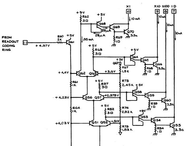
When the ring is left floating, it is pulled up to 5 volts. In this case, the voltages are as shown in the schematic. Q62, Q56, and Q51 are on, and Q63, Q57, and Q52 are off. Current is allowed to flow out of the base of Q68, and consequently the darlington pair of Q69 and Q70 is turned on, sinking current from the X1 pin of the M94.
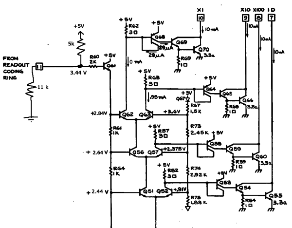
When a 10x probe is connected, the voltage of the probe pin ring is determined by a voltage divider formed by the 5 kΩ resistor (to +5 V) in the scope and the 11 kΩ resistor (to ground) in the probe. The voltage at pin 11 of the M94 is 3.44 V. Q62 is off and Q63 is on. Current is allowed to flow out of the base of Q64, and Q65 and Q66 are on. The X10 pin of the M94 is sinking current.
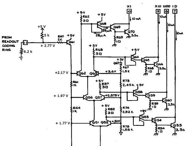
When a 100x probe is connected, the voltage at pin 11 is 2.77 V. Q57 is on and Q56 is off. Since Q56 is off, there is no tail current in the Q62/Q63 pair. The collector of Q57 pulls current from the base of Q58, which turns on Q59 and Q60. The X100 pin sinks current.
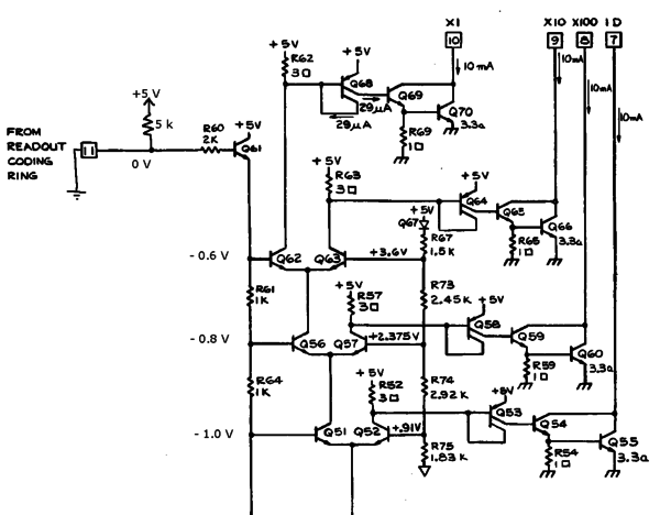
Some probes have an "identify" button. When pressed, that button shorts the probe detect pin to ground. In that situation, pin 11 of the M94 is at ground potential and the identify switch is sinking 200 μA from the 5 kΩ pullup resistor. Q52 is on. Q51 is off, and there is no tail current in Q56/Q57, and the same with Q62/Q63. The ID pin is sinking current.
Used in
Datasheet
Links
-
M94 as U80 in 485


