492: Difference between revisions
No edit summary |
|||
| Line 69: | Line 69: | ||
Front panel inputs/outputs are: | Front panel inputs/outputs are: | ||
* RF INPUT | * RF INPUT (50 Ω [[N connector]]) – Input for RF signals to 21 GHz. If input signal has a DC component, use a blocking capacitor | ||
* CAL OUT [[BNC connector]] | * CAL OUT ([[BNC connector]]) – Provides 100 MHz, –20 dBm signal and a comb of frequency markers 100 MHz apart | ||
* 1ST LO OUTPUT [[SMA connector]] | * 1ST LO OUTPUT ([[SMA connector]]) – Output of the 1st local oscillator, must be terminated into 50 Ω when not connected. | ||
* 2ND LO OUTPUT [[SMA connector]] | * 2ND LO OUTPUT ([[SMA connector]]) – Output of the 2nd local oscillator, must be terminated into 50 Ω when not connected. | ||
* EXTERNAL MIXER RF INPUT [[TNC connector]] | * EXTERNAL MIXER RF INPUT ([[TNC connector]], 50 Ω) | ||
* Camera Power | |||
Rear panel inputs/outputs are: | Rear panel inputs/outputs are: | ||
* PROBE POWER | * PROBE POWER – Provides operating voltages (+5 V, -15 V, +15 V; 100 mA max each) for active probes | ||
* HORIZ | * HORIZ/TRIG (input, [[BNC connector|BNC]]) – In External Triggering mode, AC coupled input for trigger signals; when TIME/DIV selection is EXT, DC coupled input for horizontal sweep voltages | ||
* MARKER/VIDEO | * MARKER/VIDEO (B053575+, output, [[BNC connector|BNC]]) – interfaces the 492/492P with a TV Sideband Adapter, such as the Tek [[1405]], so a marker from the adapter is displayed on the internal video. External video applied to this connector will also be displayed if pin 1 of the ACCESSORIES connector is grounded. | ||
* | ** Opt. 42 replaces MARKER/VIDEO with 110 MHz IF (output, [[BNC connector|BNC]]) – 3 dB signal bandwidth ≥ 4.5 MHz | ||
* VERT ( | * EXT PRESELECTOR (B053574 and below) (output, [[BNC connector|BNC]]) – variable voltage (approx -0.2 V to +10 V) proportional to center frequency, for preselector bands of Opt. 01 instruments, to drive an external preselector | ||
* PEN LIFT ( | * HORIZ (output, [[BNC connector|BNC]]) – 0.5 V/div horizontal signal | ||
* 10 MHz IF ( | * VERT (output, [[BNC connector|BNC]]) – Video signal with 0.5 V/Div | ||
* J104 ACCESSORY (B053575 | * PEN LIFT (output, [[BNC connector|BNC]]) – TTL compatible signal to lift the pen of a chart recorder during sweep retrace. In Opt. 42 instruments this port may also be used for inputting external video if pin 1 of the ACCESSORY connector is grounded. | ||
* IEEE STD 488 PORT [[GPIB interface]] | * 10 MHz IF (output, [[BNC connector|BNC]]) – Output of the 10 MHz IF | ||
* J104 ACCESSORY (B053575+ only), female [[DB25 connector]] – Provides bidirectional access to the instrument bus. | |||
* IEEE STD 488 PORT [[GPIB interface]] – Added to all "P" suffixed instruments | |||
==Pictures== | ==Pictures== | ||
Revision as of 07:44, 9 December 2019

The Tektronix 492 is a spectrum analyzer with a frequency range of 10 kHz to 21 GHz in coax, and up to 325 GHz with external waveguide mixers (492PGM N/A). The P suffix designation indicates GPIB Programmability. The minimum resolution bandwidth is 100 Hz, and provides measurement resolution proportional to the frequency accuracy or span. With non-volatile memory (NVRAM) you can save up to 9 waveform displays, up to 10 complete front panel measurement parameter setups, and 8 K for programming macros of commonly used routines.
The single and delta markers provide direct readout of frequency and amplitude information of any point along any displayed trace. Or, get the relative (delta) frequency and amplitude information between any two points along any displayed trace or between traces.
Additional features include continuous resolution frequency tuning, up to 90 dB viewable dynamic range, built-in frequency counters, sensitivities to -134 dBm, built-in intelligence for signal processing/marker functions, push button Occupied-Bandwidth/Noise Normalization functions, macro capability with nonvolatile memory, optional switch-selectable 50/75Ω impedances, GPIB Programming, and optional MATE/CIIL Compatibility for military applications.
Key Specifications
| Frequency Range |
|
|---|---|
| Frequency Span Range (plus 0 Hz and MAX) | 492BP: 100 Hz/div to 10 GHz/div; 492PGM: 200 MHz to 1 GHz; both in 1, 2, 5 sequence |
| Resolution Bandwidth Range (-6 dB bandwidth) | 492BP: 100 Hz to 3 MHz; 492PGM: 1 kHz to 3 MHz; both in decade steps |
| RF Input impedance | 50Ω |
| Maximum Safe Input Power | CW: +30 dBm (1 W); Pulse: 75 W Pk (1 µS pulse, 0.1% duty factor) |
| RF Attenuator Range | 0 dB to 60 dB, 10 dB steps |
| Reference Level Range | -117 dBm to +30 dBm |
| Sweep Speed Range | 10 sec/div to 20 µs/div in 1, 2, 5 sequence |
| Video Bandwidth Range | 492BP: 0.3 Hz to 30 kHz; 492PGM: 3 Hz to 30 kHz |
| Triggering Modes | Free Run, Line, Video, Single, External |
| Displayed Average Noise | −30 dBm to −131 dBm |
| Display Dynamic Range | 492BP: 90 dB; 492PGM: 80 dB |
| Calibrator (Cal out) | 50Ω, -20 dBm ±0.3 dB at 100 MHz |
| Included Accessories | Operator’s Manual; Programmer Manual; 6-ft 50Ω coaxial cable N-N; 18-inch 50 Ω coaxial cable BNC-BNC; N male to BNC female adapter; rear connector shield; Power Cord; spare fuses; CRT filter set consisting of amber and gray light filters plus mesh filter, 492PGM includes gray CRT filter (no filter set) |
| Weight | 492BP: 21.76 kg (47 lbs) 492PGM: 21.3 kg (46 lbs) |
| Power | 90 − 132 VAC, 48 to 440 Hz; 180 – 250 VAC, 48 to 440 Hz. At 115 VAC, 60 Hz, 210 W max |
| Operating Atmospherics | Temperatures: -15 °C to +55 °C; Humidity: Five cycles (120 hours) MIL-STD-810; Altitude: Up to 4.6 km (15,000 ft) |
| GPIB Characteristics | In accordance with IEEE Standard 488-1978 implemented as SH1, AH1, T5, L3, SR1, RL1, PP1, DC1, DT1, and C0 |
Options
- Opt. 07: 75Ω dBmV input and calibration in addition to the normal 50Ω dBm input and calibration. (Not combinable with Opt. 21 and 22; no external mixer capability). Include 42-inch 75Ω BNC-BNC coax cable and BNC male to “F” female adapter.
- Opt. 21: (492BP) High performance 18 to 40 GHz WM490 Series Waveguide Mixer Set
- Opt. 22: (492BP) Same as Opt. 21 plus WM490U (40-60 GHz) Waveguide Mixer
- Opt. 23: GRASP software, PC2A interface, and GPIB cable
- Opt. 27: Epson LT-386SX, GRASP software, PC2A interface, and GPIB cable
- Opt. 28: Compaq Deskpro 386S, Model 40, GRASP software, PC2A interface, and GPIB cable
- Opt. 39: Non-lithium (Silver) batteries for battery-backed memory
- Opt. 41: Digital Microwave Radio Measurement Enhancement package
- Opt. 42: Replaces MARKER/VIDEO input port on the rear panel with a 110 MHz IF output port that provides a 3 dB signal bandwidth ≥ 4.5 MHz
- Opt. 45: (all except 492PGM) MATE/CIIL language interface
Links
- Comparison of 492 with 494 and 7L18
- 49x Service notes @ John Miles KE5FX
- KE5FX GPIB toolkit
- ROM replacement
- Tek 492 DIY USB interface project
- Waveguide Mixers for 492 and 7L18
- YouTube: Tektronix 492 and 496 Portable Spectrum Analyzers
Connections
Front panel inputs/outputs are:
- RF INPUT (50 Ω N connector) – Input for RF signals to 21 GHz. If input signal has a DC component, use a blocking capacitor
- CAL OUT (BNC connector) – Provides 100 MHz, –20 dBm signal and a comb of frequency markers 100 MHz apart
- 1ST LO OUTPUT (SMA connector) – Output of the 1st local oscillator, must be terminated into 50 Ω when not connected.
- 2ND LO OUTPUT (SMA connector) – Output of the 2nd local oscillator, must be terminated into 50 Ω when not connected.
- EXTERNAL MIXER RF INPUT (TNC connector, 50 Ω)
- Camera Power
Rear panel inputs/outputs are:
- PROBE POWER – Provides operating voltages (+5 V, -15 V, +15 V; 100 mA max each) for active probes
- HORIZ/TRIG (input, BNC) – In External Triggering mode, AC coupled input for trigger signals; when TIME/DIV selection is EXT, DC coupled input for horizontal sweep voltages
- MARKER/VIDEO (B053575+, output, BNC) – interfaces the 492/492P with a TV Sideband Adapter, such as the Tek 1405, so a marker from the adapter is displayed on the internal video. External video applied to this connector will also be displayed if pin 1 of the ACCESSORIES connector is grounded.
- Opt. 42 replaces MARKER/VIDEO with 110 MHz IF (output, BNC) – 3 dB signal bandwidth ≥ 4.5 MHz
- EXT PRESELECTOR (B053574 and below) (output, BNC) – variable voltage (approx -0.2 V to +10 V) proportional to center frequency, for preselector bands of Opt. 01 instruments, to drive an external preselector
- HORIZ (output, BNC) – 0.5 V/div horizontal signal
- VERT (output, BNC) – Video signal with 0.5 V/Div
- PEN LIFT (output, BNC) – TTL compatible signal to lift the pen of a chart recorder during sweep retrace. In Opt. 42 instruments this port may also be used for inputting external video if pin 1 of the ACCESSORY connector is grounded.
- 10 MHz IF (output, BNC) – Output of the 10 MHz IF
- J104 ACCESSORY (B053575+ only), female DB25 connector – Provides bidirectional access to the instrument bus.
- IEEE STD 488 PORT GPIB interface – Added to all "P" suffixed instruments
Pictures
-
-
-
-
-
-

-

-
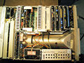
Internal top view
-