494

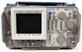
The Tektronix 494 is a spectrum analyzer with a frequency range of 10 kHz to 21 GHz in coax, and up to 325 GHz with external waveguide mixers. The P suffix designation indicates GPIB Programmability.
In 1988, the 494A /494AP successor model was introduced.
Key Specifications
| Frequency Range |
|
|---|---|
| Frequency Span | 50 Hz/Div to 500 MHz/Div in 1–2–5 sequence, plus 0 Hz and MAX |
| Resolution Bandwidth | 30 Hz, then 100 Hz to 1 MHz in decade steps (-6 dB) |
| RF Input | 50 Ω, max. +30 dBm (1 W) CW or 75 W peak pulse (1 µs, 0.1% duty factor) |
| RF Attenuator | 0 dB to 60 dB, 10 dB steps |
| Reference Level | –117 dBm to +40 dBm |
| Sweep Speed | 10 sec/div to 20 µs/div in 1, 2, 5 sequence |
| Video Bandwidth Filter | Normal, Wide: 1/30, or Narrow: 1/300 of resolution bandwidth |
| Triggering Modes | Free Run, Line, Video, Single, External |
| Display Dynamic Range | 80 dB |
| Calibrator (Cal out) | 50 Ω, –20 dBm ±0.3 dB at 100 MHz |
| Weight | 24 kg (52 lbs) with standard accessories |
| Power | 90 − 132 VAC, 48 to 440 Hz; 180 – 250 VAC, 48 to 440 Hz, 210 W max |
| Operating Environment | –15 °C to +55 °C, Humidity: Five cycles (120 hours) MIL-STD-810; Altitude: Up to 4.6 km (15,000 ft) |
Options
- Opt. 08: Delete external Mixer capability
- Opt. 12: Help mode text in English + German
- Opt. 13: Help mode text in English + French
- Opt. 14: Help mode text in English + Spanish
- Opt. 20: General Purpose 12.4-40 GHz Waveguide Mixer Set
- Opt. 21: High performance 18 to 40 GHz WM490 Series Waveguide Mixer Set
- Opt. 22: Same as Opt. 21 plus WM490U (40-60 GHz) Waveguide Mixer
- Opt. 30: Rackmount with front panel I/O
- Opt. 31: Rackmount with rear panel I/O
- Opt. 32: Benchmount
- Opt. 41: Digital Microwave Radio Measurement Enhancement package: Provides wider bandwidth preselector, 30Hz video filter with 100 kHz resolution bandwidth and a 5 MHz/Div span.
- Opt. 42: Replaces MARKER/VIDEO input port on the rear panel with a 110 MHz IF output port that provides a 6 dB signal bandwidth ≥ 5 MHz
- Opt. 45: MATE/CIIL language interface
Links
Connections
Front panel inputs/outputs are: RF INPUT 50Ω (N connector), CAL OUT (BNC connector), LO OUTPUTS (SMA connectors), EXTERNAL MIXER RF INPUT (TNC connector), and Camera Power. The LO outputs can be used to connect an external waveguide mixer like the WM490 series, or to connect a TR503 tracking generator.
Rear panel inputs/outputs are: PROBE POWER (Provides operating voltages (+5V, -15 V, +15 V; 100 mA max each) for active probes); HORIZ|TRIG (EXT IN) BNC connector (A dual function connector: When in External Triggering mode the connector is an AC coupled input for trigger signals. When the TIME/DIV selection is EXT the connector is a DC coupled input for horizontal sweep voltages); MARKER/VIDEO (EXT IN) BNC connector (Available on instruments without Opt. 42 only. See 110 MHz IF for Opt. 42 instruments. This connector interfaces the spectrum analyzers with a Tektronix 1405 TV Adapter to display an externally-generated marker) 110 MHz IF (OUTPUT) BNC connector (Available on Opt. 42 utilizing the HORIZ (OUTPUT) connector. This connector provides 110 MHz IF output with a bandwidth greater than 5 MHz. Input external video signals into the PEN LIFT connector); HORIZ (OUTPUT) BNC connector (Supplies a 0.5 V/div horizontal signal); VERT (OUTPUT) BNC connector (Provides access to the video signal with 0.5 V for each division of displayed video above or below the center line.)
NOTE: Both HORIZ and VERT output signals are driven from digital storage if it is on. Both signals are driven from the analyzer sweep and video amplifier stage if digital storage is off;
PEN LIFT (OUTPUT) BNC connector (Provides access to a TTL compatible signal to lift the pen of a chart recorder during sweep retrace. This signal is always derived from the spectrum analyzer sweep. In Opt. 42 instruments, use this connector to input external video signals if pin 1 of the ACCESSORIES connector is grounded; 10 MHz IF (OUTPUT) BNC connector (Provides access to the output of the 10 MHz IF); EXT REF IN BNC connector (A 50Ω input for a 1, 2, 5, or 10 MHz external reference signals, within -15 dBm to +15 dBm level. Input signals must be a sinewave with a duty cycle symmetry of 40% to 60%, or ECL or TTL); J104 ACCESSORY female DB25 connector (Provides external video input selector on Pin 1 and external preselector out on Pins 2 and 3, Pin 5 is ground.); IEEE STD 488 PORT GPIB interface (Added to all "P" suffixed instruments)
Accessories originally included
Operator’s Manual; Programmer Manual; 6-ft 50Ω coaxial cable N-N; 18-inch 50Ω coaxial cable BNC-BNC; N male to BNC female adapter; Diplexer Assembly; Power Cord; spare fuses; CRT filter set consisting of amber and gray light filters plus mesh filter
Pictures
-
-
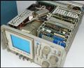
Internal top view
-
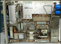
Internal bottom view


Components
Some Parts Used in the 494
| Part | Part Number(s) | Class | Description | Used in |
|---|---|---|---|---|
| 151-0261-00 | 151-0261-00 | Discrete component | dual PNP transistor | AM501 • AM502 • CG5001 • CG551AP • FG501 • FG502 • FG503 • OF150 • OF151 • OF152 • OF235 • OS261 • RM502A • R1140 • R5030 • R5031 • R7912 • 067-0679-00 • 067-0807-00 • 1101 • 1140A • 1141 • 1142 • 1350 • 145 • 1450 • 1480 • 1481 • 1482 • 1485 • 1501 • 1801 • 1900 • 1910 • 1980 • 213 • 26A1 • 26A2 • 2620 • 285 • 3A9 • 3A10 • 3S1 • 3S2 • 3S5 • 3S6 • 432 • 434 • 4501 • 454 • 4601 • 4602 • 4610 • 4612 • 4620 • 4632 • 4634 • 4701 • 475 • 492 • 492A • 492AP • 494 • 494P • 496 • 496P • 5A13N • 5A20N • 5A21N • 5A22N • 5A26 • 5L4N • 502A • 5030 • 5031 • 576 • 690SR • 7A22 • 7A29 • 7B51 • 7B71 • 7J20 • 7L5 • 7S11 • 7S12 • 7912AD |
| 155-0035-00 | 155-0035-00 • 155-0116-00 | Monolithic integrated circuit | quad op-amp | 3110 • 3S7 • 3T7 • 492 • 492A • 492AP • 492P • 494 • 494P • 496 • 496P • 4010 • 4011 • 4012 • 4013 • 7L5 • 7L12 • 7L13 • 7L14 • 7L18 • 7S11 • 7T11 • 7S12 • S-6 • 1461 • 4602 • P7001 • 613 • 653 |
| 155-0106-00 | 155-0106-00 | Monolithic integrated circuit | normalizer | J20 • 492 • 492A • 492AP • 492P • 494 • 494P |
| 155-0157-00 | 155-0157-00 | Monolithic integrated circuit | digital storage vertical control | 7L5 • 7L14 • 7L18 • 491 • 492 • 492A • 492BP • 492PGM • 494 • 494A • 495 • 496 • 497P |
| 155-0158-00 | 155-0158-00 | Monolithic integrated circuit | digital storage horizontal control | 7L5 • 7L14 • 7L18 • 491 • 492 • 492A • 492BP • 492PGM • 494 • 494A • 495 • 496 • 497P |
| 155-0285-00 | 155-0285-00 | Hybrid integrated circuit | leveling circuit | 494 |
| 155-0286-00 | 155-0286-00 | Hybrid integrated circuit | distribution amplifier | 494 |
| 155-0287-00 | 155-0287-00 | Hybrid integrated circuit | mixer | 494 |