S-2: Difference between revisions
No edit summary |
No edit summary |
||
| Line 32: | Line 32: | ||
==Repair issues== | ==Repair issues== | ||
The input should always be terminated when not in use because the [[sampling diodes]] are easily damaged by excessive inputs or static discharge. See that article for possible replacements. | *The input should always be terminated when not in use because the [[sampling diodes]] are easily damaged by excessive inputs or static discharge. See that article for possible replacements. | ||
*The ground contact of R4 can become intermittent, causing the input impedance to go high or fluctuating. The cure is to disassemble the sampler incuding the sampler board covers, and then carefully bend the ground tabs of the input termination resistor outward. | |||
==Pictures== | ==Pictures== | ||
| Line 46: | Line 47: | ||
Tek s2 amp side.jpg | S-2 interior, amplifier board side | Tek s2 amp side.jpg | S-2 interior, amplifier board side | ||
Tek s2 bridge in place.jpg | Sampling diodes in place | Tek s2 bridge in place.jpg | Sampling diodes in place | ||
Tek s2 input term r4.jpg | Input termination resistor | Tek s2 input term r4.jpg | Input termination resistor R4 | ||
Tek s2 sampler r.jpg | Sampler board, right | Tek s2 sampler r.jpg | Sampler board, right | ||
Tek s2 sampler l.jpg | Sampler board, left | Tek s2 sampler l.jpg | Sampler board, left | ||
Revision as of 14:26, 25 March 2020
Template:Plugin Sidebar 2 The Tektronix S-2 Sampling Head plug-in provides a single GR-874 50 Ω input with a 75 ps risetime.
The S-2 can be used in the 7000 series and 3S series of sampling plug-ins. It provides an internal trigger pickoff signal for internal triggering. Noise is specified as less than 10 mV.
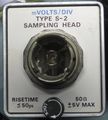
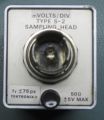
When the S-2 was first introduced, the rise-time specification was 50 ps, but that was not achieved in practice, so the rise-time specification was revised to be 75 ps.
The interface between the GR-874 connector and the printed circuit board is described in US Patent 3,426,311.
Key Specifications
| Rise time | 75 ps |
|---|---|
| Bandwidth | 4.66 GHz eq. |
| Input voltage | −1 to +1 V (max. −5 to +5) |
Repair issues
- The input should always be terminated when not in use because the sampling diodes are easily damaged by excessive inputs or static discharge. See that article for possible replacements.
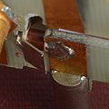
- The ground contact of R4 can become intermittent, causing the input impedance to go high or fluctuating. The cure is to disassemble the sampler incuding the sampler board covers, and then carefully bend the ground tabs of the input termination resistor outward.
Pictures
-
-
early S-2 with tr ≤ 50ps on front
-
early S-2 with overstickered tr ≤ 50ps
-
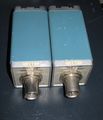
two S-2 engineering sample (late model)
-
S-52 and S-2 give 76 ps rise-time together
-
schematic
-
S-2 interior, strobe board side
-
S-2 interior, amplifier board side
-
Sampling diodes in place
-
Input termination resistor R4
-
Sampler board, right
-
Sampler board, left
-
Diode holder slides out
-
Sampler board underside
-
S-2 with amplifier board removed
-
Strobe board underside
-
S-2 with strobe board removed
-
S-2 pulse response


