TG501: Difference between revisions
No edit summary |
Jaredcabot (talk | contribs) (Added manual) |
||
| Line 2: | Line 2: | ||
manuals= | manuals= | ||
'''TG501''' | '''TG501''' | ||
* [[Media:070-1576-00.pdf| | * [[Media:070-1576-00.pdf|TG501 Manual 070-1576-00]] | ||
* [[Media:070-1576-02.pdf| | * [[Media:070-1576-02.pdf|TG501 Manual 070-1576-02]] (OCR, stitched schematics) | ||
* [[Media:TG501 schematics.pdf| | |||
* [[Media:050-1425-02.pdf|TG501 Product Mod 050-1425-02]] | |||
* [[Media:TG501 schematics.pdf|TG501 Schematics, stitched]] | |||
'''TG501A''' | '''TG501A''' | ||
* [[Media:070-7373-00.pdf| | * [[Media:070-7373-00.pdf|TG501A Manual 070-7373-00]] | ||
}} | }} | ||
There is also a TG501A. | There is also a TG501A. | ||
Revision as of 02:05, 13 May 2023
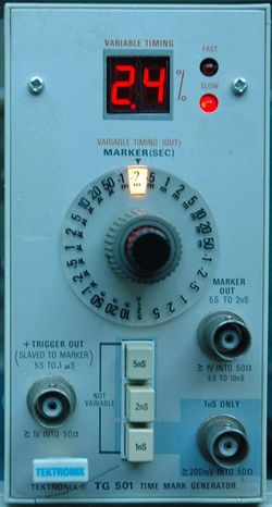
The Tektronix TG501 is a time-mark generator plug-in for the TM500 system.
There is also a TG501A.
Note the output must be terminated into 50 Ω or there may be no signal at all.
Key Specifications
| Interval | 1 ns to 5 s in 1−2−5 sequence |
|---|---|
| Timing accuracy | Stability 1×10⁻⁵, long-term drift 1×10⁻⁵ per month (with Option 1, 5×10⁻⁷ / 1×10⁻⁷ per month) |
| Error Readout | Accuracy 1 digit (±0.1% points), Range to ±7.5% |
| Amplitude | ≥1 V peak on 5 s through 10 ns; ≥750 mVp-p on 5 ns and 2 ns; ≥200 mVp-p on 1 ns (separate output) (all into 50 Ω) |
| Trigger Output | Slaved to marker output from 5 s through 100 ns. Remains at 100 ns for all faster markers |
| External Reference Input | 1 MHz, 5 MHz or 10 MHz; TTL compatible (internally hard wired so output frequencies counted down to 1 MHz) |
Rear Interface Signals
| Connector Pin | Description | |
|---|---|---|
| Signal | Return | |
| 28A | 27A | Marker Out (requires front BNC disconnection) |
| 27B | 28B | Trigger Out (requires front BNC disconnection) |
| 25A | 26A | Internal 1 MHz Clock Out (TTL) |
| 24B | 25B | External Clock Input |
| 26B | 22B | Data Good (High when BCD data valid) |
| 17A..20A | 22B | bit 4..1 BCD Display data, MSD |
| 21A..24A | 22B | bit 4..1 BCD Display data, LSD |
| 16A | 22B | Fast=Low, Slow=High |
Internals
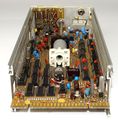
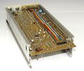
The TG501 internally produces a 1 MHz reference clock, either from an internal crystal oscillator, or from an externally supplied frequency.
A 100 MHz VCO is phase-locked to this reference frequency (in fixed-frequency mode) or to the output of a variable 1 MHz astable multivibrator (in variable frequency mode). When the variable oscillator is in use, its frequency is digitally compared to the fixed 1 MHz reference and displayed as a deviation in percent with a pair of LEDs indicating the sign (fast or slow).
A chain of dividers running off the 100 MHz clock provide the selectable output markers.
The 1 ns output uses a 152-0503-00 step-recovery diode.
Links
- See the TG501/Repairs page for repair information.
- Tek TG501A Time Mark Gen Restoration by NFM @ YouTube
- TG501 Repair and Calibration by Zenwizard Studios @ YouTube
- TG501 In-Depth Troubleshooting of a Stubborn Unit by Zenwizard Studios @ YouTube
- TG501 In-Depth Troubleshooting of a Stubborn Unit Part 2 by Zenwizard Studios @ YouTube
Pictures
TG501
-
TG501 early version
-
TG501 late version
-
-
-
-
-
-
-
-
TG501 early version
-
TG501 early version
-
TG501 output waveform


