129: Difference between revisions
No edit summary |
mNo edit summary |
||
| Line 6: | Line 6: | ||
|summary=Plugin power supply | |summary=Plugin power supply | ||
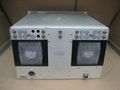
|image=Tek_129_front.jpg | |image=Tek_129_front.jpg | ||
|caption=Tek 129 | |caption=Tek 129 Front | ||
|introduced=1964 | |introduced=1964 | ||
|discontinued=(?) | |discontinued=(?) | ||
| Line 39: | Line 39: | ||
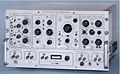
Tek 129 rear.jpg | Tek 129 rear.jpg | ||
Tek_129.jpg | Tek_129.jpg | ||
Tek 129 dimensional.png|Dimensional | Tek 129 dimensional.png | Dimensional Drawing | ||
Tek 129 interconnecting sockets.png|Interconnecting | Tek 129 interconnecting sockets.png | Interconnecting Sockets | ||
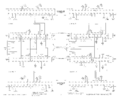
Tek 129 power supply.png|Power | Tek 129 power supply.png | Power Supply | ||
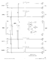
Tek 129 passive circuit card.png|Passive | Tek 129 passive circuit card.png | Passive Circuit Card | ||
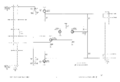
Tek 129 cathode follower card.png|Cathode | Tek 129 cathode follower card.png | Cathode Follower Card | ||
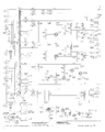
Tek 129 output and monitor circuit.png|Output | Tek 129 output and monitor circuit.png | Output & Monitor Circuit | ||
</gallery> | </gallery> | ||
Revision as of 09:11, 28 September 2023

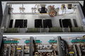
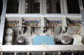
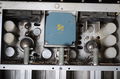
The Tektronix 129 is an enclosure and power supply allowing up to four 560-series plug-ins to be used as freestanding instruments. The 129 has a fan and a 150 °F (65 °C) thermal cutoff.
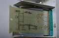
Each plug-in bay in the 129 has an output circuit card. The deflection signal output on pins 17 and 21 of the plug-in drive the output circuit card. There are two varieties of output circuit card: active (cathode-follower) and passive. To use sampling plug-ins in the 129, active output circuit cards are required.
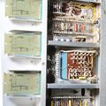
The power supply of the 129 is linear and consists of a power transformer followed by silicon rectifiers, electrolytic capacitors, and then regulators. Not all of the supply voltages are regulated. A ZZ1000 tube is used as the voltage reference. The regulators (feedback amplifiers and output tubes) are all tube, except for the high-current −12.2 V regulated supply. This one uses bipolar transistors for the feedback amplifier and output device. The −12.2 V supply is independently fused. The other supplies are not independently fused. The 129 has a 6.25 A fuse on the primary of the mains transformer.
Pictures
-

-
-

-
-
-
-
-
-
-
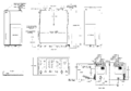
Dimensional Drawing
-
Interconnecting Sockets
-
Power Supply
-

Passive Circuit Card
-
Cathode Follower Card
-
Output & Monitor Circuit


