GR-874 connector: Difference between revisions
No edit summary |
(Convert to internal links.) |
||
| Line 16: | Line 16: | ||
==Links== | ==Links== | ||
* [ | * [[Media:GenRad Experimenter Oct 1948.pdf | A Radically New Coaxial Connector for the Laboratory. General Radio Experimenter, Volume XXIII No.5, October 1948]] | ||
* [ | * [[Media:GenRad Experimenter Oct 1961.pdf | New and Improved Coaxial Connectors. General Radio Experimenter, Volume 35 No.10, October 1961]] | ||
* [ | * [[Media:Gr874 1973 gr catalog.pdf | GR-874 Section of 1973 General Radio Catalog (PDF)]] | ||
* [[wikipedia:GR_connector|GR connector]] @ Wikipedia | * [[wikipedia:GR_connector|GR connector]] @ Wikipedia | ||
* [[Patent US 2548457A|US Patent #2,548,457A, Coaxial connector for high-frequency transmission lines]]. Filed 10 Jan 1947, granted 10 Apr 1951. | * [[Patent US 2548457A|US Patent #2,548,457A, Coaxial connector for high-frequency transmission lines]]. Filed 10 Jan 1947, granted 10 Apr 1951. | ||
Revision as of 23:53, 29 November 2023

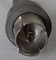
General Radio 874 (GR-874) connectors are hermaphroditic (asexual) coaxial RF connectors developed by Eduard Karplus at General Radio in the late 1940s, initially for applications up to "4500 Mc" (4.5 GHz).
GR-874 connectors are carefully engineered to keep a constant impedance throughout the signal path, by varying connector diameters between free-air and dielectrically supported sections. These connectors therefore exhibit very little reflection and are well suited for frequencies up to 9 GHz and pulse applications. For higher frequencies a smaller connector is required to avoid the excitation of wave guide modes.
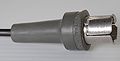
Most GR-874 connectors came in 50 Ω impedance. Versions for 75 Ω and 125 Ω were also available using the same ground shield and housing, but different (thinner) center pin geometry. The Tektronix 519 uses the 125 Ω GR-874 variant.
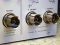
The regular 50 Ω version is used in the 1S1, 1S2, 3S1, 3S7, 3T7, 4S1, 4S2, 5T1, 5T1A, 5T3, 7M11, N, S-1, S-2, 106, 109, 110, 113, 191, 261, 280, 281, 282, R293, 661, P6025, P6032, P6051, 017-0086-00, 017-0088-00, 035-5031-00, 067-506, 067-0511-00, 067-0513-00, 067-0578-99, 067-0594-00, 067-0832-01, and possibly others.
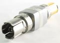
Different versions of the connector have different maximum voltage ratings; 1000 V is typical. There are locking and non-locking versions.
By the 1970s, GR-874 connectors were being supplanted by SMA connectors in test equipment, see e.g. the progression from the S-1 to the S-4 sampling heads, also motivated by the higher bandwidth requirements.
GR-874 connectors and adapters continue to be available through IET Labs, Max-Gain Systems, Pasternack and possibly others.
Links
- A Radically New Coaxial Connector for the Laboratory. General Radio Experimenter, Volume XXIII No.5, October 1948
- New and Improved Coaxial Connectors. General Radio Experimenter, Volume 35 No.10, October 1961
- GR-874 Section of 1973 General Radio Catalog (PDF)
- GR connector @ Wikipedia
- US Patent #2,548,457A, Coaxial connector for high-frequency transmission lines. Filed 10 Jan 1947, granted 10 Apr 1951.
- MGS sales list of GR874 hardware
- 017-051/017-052/017-053/017-055 adapters
Pictures
-
-
-
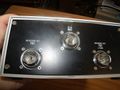
GR-874 connectors on a 106 pulse generator
-
50 Ω GR-874 connector
-

125 Ω GR-874 connector
-
-
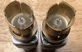
Two 75 Ω and one 50 Ω GR-874 connectors
-
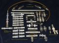
An assortment of GR-874 connectors and adapters
-
GR-874 50 Ω Terminator
-
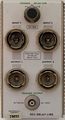
7M11 delay line front panel with four GR-874 connectors
-
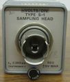
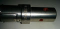
GR-874 connector on S-1 sampling head
-
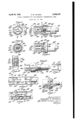
Patent drawings from US2548457


