1A7: Difference between revisions
No edit summary |
mNo edit summary |
||
| Line 55: | Line 55: | ||
! Common mode | ! Common mode | ||
|- | |- | ||
| 10 μV/Div to 10 mV/Div || ±0. | | 10 μV/Div to 10 mV/Div || ±0.3 V || ±0.3 V || ±10 V | ||
|- | |- | ||
| 20 mV/Div to 0.1 V/Div || | | 20 mV/Div to 0.1 V/Div || ±3 V || ±3 V || ±100 V | ||
|- | |- | ||
| 0.2 V/Div to 1 V/Div || | | 0.2 V/Div to 1 V/Div || ±30 V || ±30 V || ±500 V | ||
|- | |- | ||
| 2 V/Div to 10 V/Div || | | 2 V/Div to 10 V/Div || ±300 V || ±300 V || ±500 V | ||
|- | |- | ||
|} | |} | ||
Latest revision as of 20:24, 3 July 2024
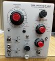
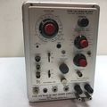
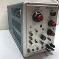
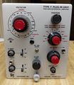
Replacing Types D and E, the Tektronix Type 1A7 is a high-sensitivity differential plug-in for 500-series scopes. It senses down to 10 μV/Div, either AC or DC-coupled. It is possible to apply up to ±300 mV offset to the reading while maintaining sensitivity. Upper and lower cutoff frequency is selectable on the front panel. Maximum bandwidth is 500 kHz, and common-mode rejection is 50,000 to 1.
Type 1A7's front end is a matched quad of 8393 nuvistors, with two in parallel - to reduce noise - on each input. These tubes are in temperature-equalizing housings, and mounted on a rubber-isolated subchassis. The "coarse" balance adjustment controls the relative heater voltages on the 8393's.
Type 1A7 (initially named Type F) was designed by John Addis and introduced in 1966. Lasting only two years before being replaced by the redesigned 1A7A, Type 1A7 is the shortest-lived 500-series plugin. In 1968, modification kit 040-0485-00 was offered to convert existing instruments to FET front end to reduce drift and microphonics.
Origins
John Addis says:
Type D was a mid-1950s DC-coupled 1 mV/div differential plugin (350 kHz at 1 mV/div, but 2 MHz at 50 mV/div) for the 530 and 540 series of mainframes. Similarly, Type E was a mid-1950s AC-coupled 50 μV/div differential plugin (30 kHz at 50 μV/div, but 60 kHz at 0.5 mV/div).
By 1963, they had become dated by later plugins in the 560 series (e.g. 3A3, 2A61). Personally, I thought this was too bad as the 530/540 series was the premier scope line being overtaken by the lower-priced line.
Roy Hayes sat near me in Russ Fillinger’s group in Sunset South, Building 81, and he had been working on Type 3A3, a very nice dual trace, DC coupled 100 μV/div (500 kHz at all sensitivities and a 5 kHz single pole BWL filter) differential amplifier plugin for the 560 series. It had very high common mode rejection due to some more sophisticated circuits than the D or E. I really liked several circuit ideas in the 3A3.
I proposed to Russ a DC coupled plugin for the 530/540 series (the "Letter" series) with the idea of combining the outdated D and E plugins and extending the DC sensitivity from 1 mV to 10 μV, rather daring for a vacuum tube front end. I included the high common-mode rejection circuitry from the 3A3 and added a full range of bandwidth limit selections, at both the low and high frequency ends of the spectrum. The amplifier low frequency limit included DC as the first selection. Russ went for it even though it was not part of his focus, the 560 series. It took exactly a year to design, and by the time I was finished, I had added another feature, wide range differential DC offset.
It was supposed to be the Type F plugin, because it did not have the bandwidth extension of the 1A series (50 MHz in the 547), but to my chagrin, management decided that it would be a 1A series anyway and renamed it the 1A7. (I probably have the only Type F plugin.) Management also changed the nice clear-skirt VOLTS/DIV knob (a larger version of the 3A3’s knob) to a boring opaque-skirt knob like older letter-series plugins. Late production versions of the 1A7 and 3A3 had JFET inputs.
Nevertheless, the exact combination of features of the 1A7 was repeated in the 1A7A (designed by Thor Hallen), in the venerable 7A22 (designed by Val Garuts), and in the 3A9 (with additional current probe input). These later three plugins made use of JFETs and all three are of the same design. That circuit, using feedback, is much better than the earlier 1A7 design.
(Correspondence May 2021)
Key Specifications
| Deflection | 10 μV/Div to 10 V/Div in 1–2–5 sequence |
|---|---|
| Input impedance | 1 MΩ // 47 pF (either input) |
| Bandwidth | 500 kHz, LF limit switchable DC, 0.1 Hz to 10 kHz in ×10 steps, HF limit switchable 100 Hz to 100 kHz in ×3/×10 steps, and 500 kHz; AC coupling 1.6 Hz |
| Signal ranges |
| Range | Differential signal | DC Offset | Common mode |
|---|---|---|---|
| 10 μV/Div to 10 mV/Div | ±0.3 V | ±0.3 V | ±10 V |
| 20 mV/Div to 0.1 V/Div | ±3 V | ±3 V | ±100 V |
| 0.2 V/Div to 1 V/Div | ±30 V | ±30 V | ±500 V |
| 2 V/Div to 10 V/Div | ±300 V | ±300 V | ±500 V |

