111: Difference between revisions
No edit summary |
Vintage dave (talk | contribs) m (Late and early rear view photos were swapped, late has the BNC and early has the UHF) |
||
| (3 intermediate revisions by one other user not shown) | |||
| Line 5: | Line 5: | ||
|series= | |series= | ||
|summary=Pretrigger Pulse Generator | |summary=Pretrigger Pulse Generator | ||
|image=Tek 111 front. | |image=Tek 111 front.jpeg | ||
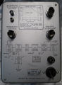
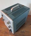
|caption=Front View | |caption=Front View | ||
|introduced=1960 | |introduced=1960 | ||
| Line 12: | Line 12: | ||
|manuals= | |manuals= | ||
* [[Media:070-252.pdf|Tektronix 111 Manual]] (PDF) | * [[Media:070-252.pdf|Tektronix 111 Manual]] (PDF) | ||
* [ | * [https://w140.com/tek_fcp/tek_type_111_factory_cal_proc.pdf Tektronix 111 Factory Calibration Procedure (PDF)] | ||
}} | }} | ||
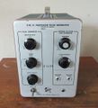
The '''Tektronix Type 111 Pretrigger Pulse Generator''' produces two pulse signals, one to trigger an oscilloscope sweep and a main output pulse to stimulate the device under test. | The '''Tektronix Type 111 Pretrigger Pulse Generator''' produces two pulse signals, one to trigger an oscilloscope sweep and a main output pulse to stimulate the device under test. | ||
| Line 39: | Line 39: | ||
Tek 111 right.jpg|Right Internal View | Tek 111 right.jpg|Right Internal View | ||
Tek 111 right internal.jpg|Right Internal View | Tek 111 right internal.jpg|Right Internal View | ||
Tek_111_rear.jpg| | Tek_111_rear.jpg|Early serial number rear view | ||
Tek_111-Rear.jpg | Rear | Tek_111-Rear.jpg | Rear | ||
Tek 111 rear2.jpg| | Tek 111 rear2.jpg|Late serial number rear view | ||
Tek 111 schem.gif|Schematic | Tek 111 schem.gif|Schematic | ||
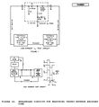
Tek 110 or 111 and type n diode measure.jpg | Tek 110 or 111 and type n diode measure.jpg | ||
Tek type 111 two triggers per pulse 1.jpeg|111 with two triggers per pulse switch | |||
Tek type 111 two triggers per pulse 2.jpeg|111 with two triggers per pulse switch | |||
Tek type 111 two triggers per pulse 3.jpeg|111 with two triggers per pulse switch | |||
</gallery> | </gallery> | ||
[[Category:Pulse generators]] | [[Category:Pulse generators]] | ||
Latest revision as of 09:20, 31 December 2023

The Tektronix Type 111 Pretrigger Pulse Generator produces two pulse signals, one to trigger an oscilloscope sweep and a main output pulse to stimulate the device under test.
The trigger pulse comes between 30 and 250 nanoseconds before the output pulse; this is controlled by a knob on the 111. This gives adequate time for the oscilloscope to start sweeping so that the leading edge of the input or output signals of the device under test can be viewed. The alternative is to have a delay line in the signal path, after the trigger pickoff, but delay lines degrade transient performance. Using a pretrigger eliminates the need for a delay line in the vertical signal path and therefore enables accurate high-speed measurements. For a stable display, low jitter of the delay between pretrigger and main pulse is essential.
Key Specifications
| Pulse repetition rate | 10 Hz to 100 kHz, or by external trigger |
|---|---|
| Rise time | <500 ps |
| Pre-trigger | 30−250 ns variable with additional calibrated "+1 ns" switch, jitter ≤100 ps |
| Output amplitude | ≥10 V (selectable polarity) into 50 Ω |
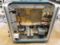
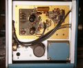
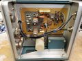
Internals
The main output pulse of the Type 111 is produced by an avalanche transistor.
Notes
The Auxiliary Equipment section in the Type N manual says the rise time is 300 ps. The 111 front panel and manual specify <500 ps.
Pictures
-
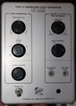
Front View
-
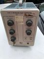
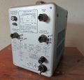
Front
-

Left Internal View
-
Left Internal View
-
Right Internal View
-
Right Internal View
-
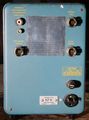
Early serial number rear view
-
Rear
-
Late serial number rear view
-
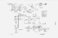
Schematic
-
-
111 with two triggers per pulse switch
-
111 with two triggers per pulse switch
-
111 with two triggers per pulse switch


