2642: Difference between revisions
No edit summary |
mNo edit summary |
||
| Line 24: | Line 24: | ||
{{Spec | Channels | 2 (optionally 4), matched ±0.075 dB (DC to 50 kHz) }} | {{Spec | Channels | 2 (optionally 4), matched ±0.075 dB (DC to 50 kHz) }} | ||
{{Spec | Transient Capture | 500 K Samples, extended to 3.5 M with Opt. 6M (6 MB) }} | {{Spec | Transient Capture | 500 K Samples, extended to 3.5 M with Opt. 6M (6 MB) }} | ||
{{Spec | | {{Spec | FFT performance | 32-bit floating point FFT, 64 tp 4096 points }} | ||
{{Spec | Spectral Lines | 25 to 1600 }} | {{Spec | Spectral Lines | 25 to 1600 }} | ||
{{Spec | Input Impedance | 1 MΩ // 200 pF }} | {{Spec | Input Impedance | 1 MΩ // 200 pF }} | ||
Revision as of 09:40, 14 April 2022

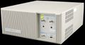
The Tektronix 2642A is an FFT analyzer with a DC to 200 kHz frequency range. It performs signal acquisition and processing, and uses a PC running MS-DOS connected via a serial port for mass storage and graphics.
It has two or four inputs with dedicated 12-bit (optionally 16-bit) ADCs, and an optional arbitrary function generator. Another option is a "zoom" feature that provides a span as small as 10 Hz about the frequency of interest.
Key Specifications
| Frequency range | DC to 200 kHz |
|---|---|
| Real-time bandwidth | 100 kHz max. (single channel autospectrum with fast additive averaging, display off, 2048 point frame size) |
| Dynamic range | 75 dB, extended to 90 dB with Opt. 16 or 17 (16-bit ADCs) |
| Channels | 2 (optionally 4), matched ±0.075 dB (DC to 50 kHz) |
| Transient Capture | 500 K Samples, extended to 3.5 M with Opt. 6M (6 MB) |
| FFT performance | 32-bit floating point FFT, 64 tp 4096 points |
| Spectral Lines | 25 to 1600 |
| Input Impedance | 1 MΩ // 200 pF |
| Max Input Level | ±30 V |
| Weight | Standard accessories: 12.3 kg (27 lbs) |
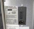
| Power | 90 − 250 VAC, 48 to 66 Hz, >120 W |
| Connections |
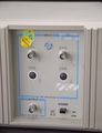
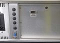
Front panel: CH1-CH4 inputs, BNC connector; Signal generator output BNC connector (50 Ω; ±10 V); |
- (Specifications based on 1994 published documentation unless otherwise specified)
Options
- Opt. 1H: Four Input Channels
- Opt. 16: Two 16-Bit Input Channels
- Opt. 17: Four 16-Bit Input Channels
- Opt. 6M: Large Data Memory (add 6 MB)
Software
Internals
The 2642 uses a National NS32CG160 32/16-bit CPU and an AT&T DSP32C Digital Signal Processor.
Pictures
-

-
-
-

-
-
-
-
-
-
-
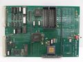
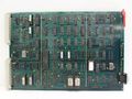
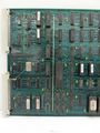
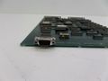
Tek 2642A CPU Board
-
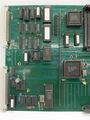
Tek 2642A CPU Board
-
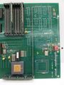
Tek 2642A CPU Board
-
Tek 2642A CPU Board
-

Tek 2642A CPU Board
-
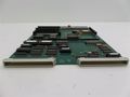
Tek 2642A Channel Controller Board
-
Tek 2642A Channel Controller Board
-
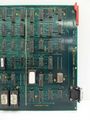
Tek 2642A Channel Controller Board
-
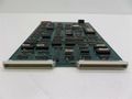
Tek 2642A Channel Controller Board
-
Tek 2642A Channel Controller Board


