506: Difference between revisions
No edit summary |
No edit summary |
||
| (8 intermediate revisions by 2 users not shown) | |||
| Line 1: | Line 1: | ||
{{Oscilloscope Sidebar |manufacturer=Tektronix |designers=|series=560-series scopes| | |||
[[ | model= 506 | | ||
summary=20 MHz scope | | |||
image=Tek 506 trace.jpg | | |||
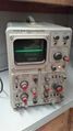
caption =506 with [[9A1]] and [[3B1]] | | |||
introduced = 1964 | | |||
discontinued = (?) | | |||
manuals= | |||
* [[Media:070-445.pdf|Tektronix 506 Manual]] (PDF) | |||
* [[Media:Tek 506 mod 129b.pdf|Tektronix 506 Mod 129B (PDF, needs OCR)]] | |||
}} | |||
The '''Tektronix Type 506''' is an oscilloscope with bandwidth above 20 MHz that uses [[560-series plug-ins|560-series horizontal plug-ins]] but special high-speed vertical plug-ins, the [[9A1]], and [[9A2]]. | |||
Like the scopes in the [[560-series_scopes|560 Series]], the 506 mainframe contains neither vertical nor horizontal amplifiers; the plug-ins directly drive the CRT deflection plates. | |||
The calibrator signal is produced by shaping mains frequency | {{MissingSpecs}} | ||
into a square wave. | |||
It is not just a simple clipping circuit. | The 506 uses the [[T5033|T5033-31-1]] CRT, which has P31 [[phosphor]]. It uses no post-deflection acceleration, total accelerating voltage is 3.5 kV. | ||
To speed up the edges, positive feedback is used. | |||
==Internals== | |||
The CRT circuit uses two [[5642]] high-voltage rectifier tubes, one for the CRT cathode voltage and one for the intensification voltage, which is applied to a second grid in the CRT. | |||
The calibrator signal is produced by shaping mains frequency into a square wave. | |||
It is not just a simple clipping circuit. To speed up the edges, positive feedback is used. | |||
A cross-connected triode and pentode form a schmitt trigger. | A cross-connected triode and pentode form a schmitt trigger. | ||
The input of the shaping circuit is the cathode of the triode | The input of the shaping circuit is the cathode of the triode and the output is the cathode of the pentode, which drives a voltage divider whose tap is selected by the front panel calibrator rotary switch. | ||
and the output is the cathode of the pentode, which drives a | |||
voltage divider whose tap is selected by the front panel | |||
calibrator rotary switch. | |||
The power supply is fairly typical of Tektronix scopes of the period. | The power supply is fairly typical of Tektronix scopes of the period. | ||
An [[OG3]] tube establishes a | An [[OG3]] tube establishes a −82 V reference voltage in the −100 V power supply section. | ||
The | The −100 V supply is then used as the reference voltage for the other power supply sections. | ||
Output tubes are used for all of the regulated supply voltages except the | Output tubes are used for all of the regulated supply voltages except the −12.2 V supply, which uses a [[2N1529]] germanium PNP transistor. | ||
which uses a [[2N1529]] germanium PNP transistor. | |||
==Pictures == | |||
<gallery> | <gallery> | ||
Tek 506 trace.jpg|506 with [[9A1]] and [[3B1]] | |||
Tek 506 331023143159.jpg | |||
Tek_506_power_supply.png|Power Supply | |||
Tek_506_crt_circuit.png|CRT Circuit | |||
Tek 506 calibrator.png|Calibrator | |||
Tek 506 interconnecting.png|Interconnecting Sockets | |||
</gallery> | </gallery> | ||
Revision as of 12:27, 20 August 2021

The Tektronix Type 506 is an oscilloscope with bandwidth above 20 MHz that uses 560-series horizontal plug-ins but special high-speed vertical plug-ins, the 9A1, and 9A2.
Like the scopes in the 560 Series, the 506 mainframe contains neither vertical nor horizontal amplifiers; the plug-ins directly drive the CRT deflection plates.
Key Specifications
- please add
The 506 uses the T5033-31-1 CRT, which has P31 phosphor. It uses no post-deflection acceleration, total accelerating voltage is 3.5 kV.
Internals
The CRT circuit uses two 5642 high-voltage rectifier tubes, one for the CRT cathode voltage and one for the intensification voltage, which is applied to a second grid in the CRT.
The calibrator signal is produced by shaping mains frequency into a square wave. It is not just a simple clipping circuit. To speed up the edges, positive feedback is used. A cross-connected triode and pentode form a schmitt trigger. The input of the shaping circuit is the cathode of the triode and the output is the cathode of the pentode, which drives a voltage divider whose tap is selected by the front panel calibrator rotary switch.
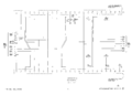
The power supply is fairly typical of Tektronix scopes of the period. An OG3 tube establishes a −82 V reference voltage in the −100 V power supply section. The −100 V supply is then used as the reference voltage for the other power supply sections. Output tubes are used for all of the regulated supply voltages except the −12.2 V supply, which uses a 2N1529 germanium PNP transistor.
Pictures
-
-

-
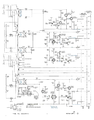
Power Supply
-
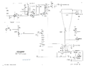
CRT Circuit
-
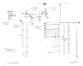
Calibrator
-
Interconnecting Sockets


