533: Difference between revisions
m (→top: clean up, replaced: {{Oscilloscope Sidebar → {{Oscilloscope Sidebar |manufacturer=Tektronix |designers=, title=Tektronix → model=) |
No edit summary |
||
| Line 1: | Line 1: | ||
{{Oscilloscope Sidebar |manufacturer=Tektronix |designers= | | {{Oscilloscope Sidebar |manufacturer=Tektronix |designers= | | ||
series=5000-series scopes | | |||
model= 533 | | model= 533 | | ||
summary=15 MHz scope | | summary=15 MHz scope | | ||
| Line 13: | Line 14: | ||
* [[Media:Tek 533a fcp sep 1966.pdf|533A Factory Calibration Procedure, September 1966]] | * [[Media:Tek 533a fcp sep 1966.pdf|533A Factory Calibration Procedure, September 1966]] | ||
}} | }} | ||
The '''Tektronix Type 533''' is a 15 MHz oscilloscope [[introduced in 1958]] | The '''Tektronix Type 533''' is a 15 MHz oscilloscope [[introduced in 1958]] | ||
that uses [[letter-series and 1-series plug-ins]]. | that uses [[letter-series and 1-series plug-ins]]. | ||
Revision as of 15:25, 9 August 2021

The Tektronix Type 533 is a 15 MHz oscilloscope introduced in 1958 that uses letter-series and 1-series plug-ins.
It is similar to a 535, but without the second, delayed timebase. Instead, it has a range of horizontal magnifiers from ×2 to ×100.
There is also a rack-mount version, the RM33. Later 533A have BNC connectors. The standard CRT for the 533 and 533A is the T5330-2. Difference between 533 and 533A is only trigger mode.
Key Specifications
| Bandwidth | DC to 15 MHz (≤ 3 dB) with Type K plug-in |
|---|---|
| Rise time | 0.024 μs |
| Line Voltage | 108/115/122/216/230/244 VAC ±10%, selected via soldering wire on transformer, 50 Hz to 60 Hz |
| Thermal Protection | Automatic resetting thermal cutout, in case internal temperature exceeds safe operating level |
| Power Consumption | 500 W with CA plug-in |
| Cooling | AC Fan |
| Trigger Modes (533) | AC/DC/AC Slow, and HF Sync |
| Trigger Modes (533A) | AC/DC/AC LF Reject, and HF Sync |
| Anode Potential | 10 kV |
| Screen Area | 6 cm × 10 cm |
| Construction | Aluminum alloy chassis. Anodized front panel |
| Weight | 61.5 lbs / 27.8 kg |
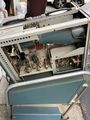
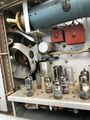
Internals
The vertical amplifier consists of a 12BY7 differential amplifier followed by a 6DJ8 cathode-follower, followed by a 6197 differential (common-cathode) output stage that drives the 200 ns L-C delay line, which drives the vertical deflection plates of the CRT.
Trigger pickoff is taken after the cathode follower stage in the vertical amplifier. There is a 6DJ8 differential trigger pickoff amplifier followed by half of a 6DJ8 a cathode follower, buffering the trigger signal.
The trigger circuit is a 6DJ8 trigger amplifier followed by a 6DJ8 Schmitt trigger. Triggering can be from the internal pickoff or from an external signal or "line" trigger, from a 6.3 V tap on the power transformer.
The 533 contains a 53 °C (128 °F) thermal cutoff. The high voltages for the CRT, +8,650 V and −1,350 V, are generated by a 60 kHz Hartley power oscillator and five 5642 high-voltage rectifier diode tubes.
Pictures
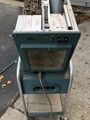
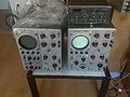
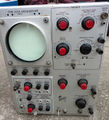
533
-

533
-
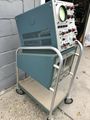
533
-
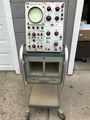
533
-

533
-
533
-

533
-

533
-
533
-

533
-
533


533A
-
front from different 533A
-
533A front
-

533A rear
-

533A
-

533A delay line
-
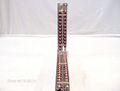
533A delay line


