7L13

The Tektronix 7L13 is a 1 kHz to 1.8 GHz Spectrum Analyzer plug-in for 7000-series scopes. From 1977 on, a modified version with coverage up to 2.5 GHz was available upon request (no official option listed in the catalog).
It is similar to the 7L12 but occupies three module bays, adds a marker function, offers resolution bandwidth down to 30 Hz, and improves sensitivity by 10 dB. It also displays the center frequency in the CRT readout as well as on a LED display.
The TR502 tracking generator is designed to work with the 7L13 up to 1.8 GHz.
Key Specifications
| Input frequency | 100 kHz – 1.8 GHz (modified version up to 2.5 GHz) |
|---|---|
| Span | 200 Hz/Div – 100 MHz/Div |
| Sweep | 1 μs/Div to 10 s/Div (1−2−5), manual, external |
| Resolution bandwidth | 30 Hz – 3 MHz in decade steps |
| Sensitivity | −128 dBm at 300 Hz to −80 dBm at 3 MHz |
| Vertical scale | 10 dB/Div, 2 dB/Div or linear |
| Reference level | −110 dBm – +30 dBm in 10 dB steps |
| Video filters | 30 kHz, 300 Hz or 10 Hz |
| Features |
|
Links
Prices
| Year | 1974 | 1976 | 1980 |
|---|---|---|---|
| Catalog price | $6,500 | $7,500 | $10,500 |
| 2020 Dollars | $34,100 | $34,100 | $33,000 |
Internals
The input signal passes a 0 to 60 dB step attenuator, a 1.8 GHz low-pass filter, and a 3 dB isolation pad before the 1st mixer, with a 1st LO frequency between 2.095 GHz and 3.895 GHz. At spans of 50 kHz/Div and below, the 1st LO (a YIG oscillator) is fixed (stabilized by a PLL) and the 2nd LO is swept.
The 1st IF filter is 10 MHz wide, centered at 2.095 GHz. With a 2nd LO at 2.2 GHz, the signal is mixed to a 105 MHz IF, amplified, filtered again (105±1.5 MHz) and mixed down to 10 MHz (3rd LO at 95 MHz).
At the 10 MHz 3rd IF, resolution filters (300 kHz L/C, 30 kHz, 3 kHz or 300 Hz crystal filters) can be selected. The detector (discrete log amplifier) and video filters follow.
The digital frequency readout is a DVM (Fairchild 3814) working off the the YIG oscillator control voltage, not a frequency counter, which is why it needs to be calibrated before use.
Custom integrated circuits used: 155-0035-00 quad opamp, 155-0042-02 Miller integrator, 155-0056-00 sweep control, 155-0088-00 legend generator.
Pictures


Display examples
-
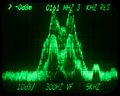
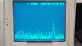
7L13 displaying a POCSAG FSK signal at 162 MHz (variable persistence storage on a 7623)
-