7L12
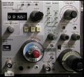
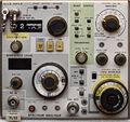
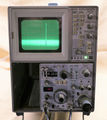
The Tektronix 7L12 is a 1.8 GHz Spectrum Analyzer plug-in for 7000-series scopes. It is a double-width plugin to be installed in the right vertical and left (or only) horizontal bay.
Early models had a mechanical reference level readout. Later, front panel outputs for 1st and 2nd LO were added to allow connecting a TR501 or TR502 tracking generator. Late models had LED reference level readout.
The 7L12 does not have the UNCAL indicator typical for spectrum analyzers that alerts the operator when the sweep speed is too fast for the given resolution. The manual advises to use the variable control to reduce sweep speed until the signal amplitudes don't change.
The Tek catalogs suggested the 7603 Opt.06 or 7613 Opt.06 as suitable mainframes.
According to Tekscope Vol.4 No.1 Jan 1972, the design teams included: Electrical Engineering – Morris Engelson, Linley Gumm, Gene Kauffman, Larry Lockwood, Gordon Long, Steve Morton, Paul Parks, Fred Telewski. Mechanical Engineering – Neal Broadbent, Jack Doyle, Al Huegli, Steve Skidmore, Leighton Whitsett. Integrated Circuits – Judy Hanson, Robert Holmes, Carolyn Moore, Rena Randle.
Key Specifications
| Input frequency | 100 kHz – 1.8 GHz (Opt.39: 2.5 GHz) |
|---|---|
| Span | 500 Hz/Div – 100 MHz/Div |
| Sweep | 1 μs/Div to 5 ms/Div (1-2-5) |
| Resolution bandwidth | 300 Hz – 3 MHz in decade steps |
| Sensitivity | −115 dBm at 300 Hz |
| Vertical scale | 10 dB/Div, 2 dB/Div or linear |
| Reference level | −100 dBm – +30 dBm |
| Video filters | 30 kHz, 300 Hz or 3 Hz |
| Features |
|
Links
- 7L12 repair vintageTek Museum @ YouTube (shows how to pull out the center board)
- 7L12 videos: #1 / #2 / #3 / #4 #5
- Tek 7L12 @ amplifier.cd
Documents Referencing 7L12
| Document | Class | Title | Authors | Year | Links |
|---|---|---|---|---|---|
| Tekscope 1971 V3 N5 Sep 1971.pdf | Article | New Products | 1971 | 7L12 • 7CT1N • 5103N • 5A13N • 5A14N • 5A22N • 5CT1N • 172 • 1501 • P6056 • P6057 • 603 • 604 • 4602 • S-3160 | |
| Tekscope 1972 V4 N1 Jan 1972.pdf | Article | Frequency Stabilization Techniques | Fred Telewski | 1972 | 7L12 |
| Tekscope 1972 V4 N1 Jan 1972.pdf | Article | Optimizing Mixer Performance Using the 7L12 Spectrum Analyzer | Gene Kauffman | 1972 | 7L12 |
| Tekscope 1972 V4 N1 Jan 1972.pdf | Article | A Microwave Spectrum Analyzer for the 7000-Series Oscilloscopes | Linley Gumm • Larry Lockwood • Morris Engelson • Al Huegli | 1972 | 7L12 |
| 7000 series brochure March 1973.pdf | Brochure | 7000 series brochure, March 1973 | 1973 | 7A11 • 7A12 • 7A13 • 7A14 • 7A15A • 7A16A • 7A17 • 7A18 • 7A19 • 7A21N • 7A22 • 7B50 • 7B53A • 7B70 • 7B71 • 7B92 • 7CT1N • 7D11 • 7D13 • 7D14 • 7D15 • 7M11 • 7L12 • 7S11 • 7S12 • 7T11 • 7704A • R7704 • 7904 • R7903 • 7603 • R7603 • 7403N • R7403N • 7313 • R7313 • 7613 • R7613 • 7623 • R7623 • P7001 | |
| Tekscope 1975 V7 N5.pdf | Article | A High-stability 100 KHz to 1.8 GHz Tracking Generator | Fred Telewski | 1975 | TR501 • TR502 • 7L12 • 7L13 |
| TekWeek (partial) October 10, 1975.pdf | Article | Spectrum analyzers require high technology | Thor Hallen • Dave Friedley | 1975 | Spectrum Analyzers • Pentrix • 7L5 • 5L4 • 7L12 • 7L13 • 1401 • 491 • 1405 • 1502 • 1503 |
| 26AX-3582-3.pdf | Application Note | FM Broadcast Measurements Using the Spectrum Analyzer | Clifford B. Schrock | 1981 | 7L12 • 7K11 • 5L4N • SG502 |
| 26W-4889.pdf | Application Note | No Loose Ends - Revised - The Tektronix Proof-of-Performance Program for CATV | 1982 | 7L12 • 7L14 • 147 • 1430 |
Patents that may apply to 7L12
| Page | Title | Inventors | Filing date | Grant date | Links |
|---|---|---|---|---|---|
| Patent US 3584174A | Push-button switch apparatus having cam actuated switch contacts and selective illumination means | Tony Sprando • Peter S Winkelmann | 1969-06-09 | 1971-06-08 | Back-lit switches • 7A11 • 7A12 • 7A13 • 7A14 • 7A16 • 7A16P • 7A22 • 7A42 • 7B42N • 7B50 • 7B51 • 7B52 • 7B53A • 7B70 • 7B71 • 7B92 • 7B92A • 7D10 • 7D11 • 7D12 • 7D114 • 7D15 • 7D20 • 7F10 • 7L5 • 7L12 • 7L13 • 7L14 • 7L18 • 7M13 • 7S11 • 7S12 • 7T11 • 067-0587-00 • 067-0587-01 • 067-0587-02 • 067-0587-10 |
Internals
The 7L12 is a traditional triple-mixing spectrum analyzer design. The input signal runs through a step attenuator (0 to 60 dB in 10 dB steps), a 1.8 GHz low-pass filter and a 3 dB pad (to isolate the mixer from LPF reflections) to a 1st mixer. The 1st LO is a YIG oscillator running at 2.095 GHz to 3.9 GHz, resulting in a 2.095 GHz 1st IF.
The 1st IF passes through a "traveling wave damper" (isolator), a 2.2 GHz LPF and a 10 MHz wide 2.095 GHz bandpass filter before reaching the 2nd mixer. The 2nd LO oscillates at 2.2 GHz (variable by ±1 MHz) for a 2nd IF of 105 MHz, which is amplified, then filtered in a 3-stage helical filter with 3 MHz bandwidth before passing through a 3rd mixer to the final 10 MHz IF, variable resolution filters, and post-resolution amplifier to the "Function IF amplifier" that implements the linear or logarithmic detector.
A phase lock circuit controls the 1st LO at spans of 0.1 MHz/Div and less, tying its frequency to a multiple of 2.21 MHz using a diode sampler employed as a mixer. The sampling gate is driven by an avalanche pulser. In phase lock, the 2nd LO is swept instead of the 1st. The fine frequency control is only operational in phase lock mode, one of the key limitations of this design.
The 7L12 includes a standard sweep circuit built around the 155-0056-00 Sweep Control (U1140) and 155-0042-02 (U1160) Miller Integrator custom ICs. The 7L12 also uses the TEK-custom quad opamp 155-0035-00 in several places.
Prices
| Year | 1971 | 1974 | 1976 | 1980 | 1984 | 1988 |
|---|---|---|---|---|---|---|
| Catalog price | $4,850 | $4,850 | $4,995 | $6,500 | $10,250 | $12,500 |
| In 2024 Dollars | $37,700 | $31,000 | $27,600 | $24,800 | $31,100 | $33,300 |
According to an internal memo, in annual sales for 1979 were estimated at 365 units.
Pictures
-
early model
-
late version with LED reference level display, front
-
later version with no uncal span
-
later and early model side by side
-
-
Left side
-
Top view
-
Right side
-
Right side toward front. The 1st mixer (bottom left) and 1st LO (large cylindrical can) are visible.
-
Bottom view
-
Bottom front
-
Bottom center. The 3-stage 2nd IF 105 MHz helical filter is visible in the middle (black cylinders).
-
Top front
-
Tektronix 7L12, center board extended
-
Tektronix 7L12, center board extended, back side. 2nd IF (105 MHz) helical filter seen near bottom.
-
105 MHz Helix filter (from Tekscope, Jan 1972)


