P6032: Difference between revisions
No edit summary |
No edit summary |
||
| (15 intermediate revisions by 5 users not shown) | |||
| Line 1: | Line 1: | ||
The '''Tektronix P6032''' is an 850 MHz cathode-follower probe, intended for use with samplers such as the [[ | {{Probe Sidebar | ||
|manufacturer=Tektronix | |||
|model=P6032 | |||
|summary=850 MHz cathode-follower probe | |||
|for=1S1 | |||
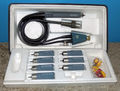
|image=Tek p6032 kit 1.jpg | |||
|caption=P6032 | |||
|introduced=1962 | |||
|discontinued=(?) | |||
|designers=Murlan Kaufman | |||
|manuals= | |||
* [[Media:070-327.pdf|Tektronix P6032 Manual]] | |||
* [[Media:Tek_P6032_preliminary_manual_1962.pdf|Tektronix P6032 Preliminary Manual]] | |||
}} | |||
The '''Tektronix P6032''' is an 850 MHz cathode-follower probe, intended for use with samplers such as the [[1S1]], [[3S1]], [[3S76]], [[4S1]], and [[4S2]]. | |||
It was designed by [[Murlan Kaufman]]. | |||
There is an [[EC1000]] subminiature triode in the probe body, which is why it gets slightly warm during operation. | There is an [[EC1000]] subminiature triode in the probe body, which is why it gets slightly warm during operation. | ||
Like all active probes, the P6032 requires power, and for this reason it has two connectors at the scope end of cable. | Like all active probes, the P6032 requires power, and for this reason it has two connectors at the scope end of the cable. | ||
There is a four-pin power connector and a 50 Ω [[GR-874 connector]] for the signal. | There is a four-pin power connector and a 50 Ω [[GR-874 connector]] for the signal. | ||
| Line 9: | Line 24: | ||
These attenuators also reduce the loading of the probe on the probed circuit. | These attenuators also reduce the loading of the probe on the probed circuit. | ||
{{BeginSpecs}} | |||
{{Spec | Bandwidth | ≥850 MHz }} | |||
{{Spec | Rise time | 0.4 ns max. }} | |||
{{Spec | Attenuation |10× to 1000× in 1-2-5 steps with supplied attenuator heads, 3× without attenuator }} | |||
{{Spec | Dynamic range | ±0.15 V × attenuation }} | |||
{{Spec | Maximum input voltage | ±0.225 V × attenuation, de-rated for CW operation for 500× and 1000× attenuator heads }} | |||
{{Spec | Input resistance | 10 MΩ with any attenuator head, 3 MΩ without attenuator head }} | |||
{{Spec | Input capacitance | 3.6 pF (10× head) to 1.3 pF (1000× head), 7 pF without attenuator head}} | |||
{{Spec | Output impedance | not specified, calibrated for 50 Ω load }} | |||
{{Spec | DC offset | ≈0.5 V (not adjustable)}} | |||
{{EndSpecs}} | |||
==Internals== | |||
The body of the probe contains a clipping line composed of what appears to be 21 mm of RG-174 coax connected to the triode's cathode at one end and open at the other end. | |||
The circuit description in the manual describes it vaguely, saying only that, "The clipping line reduces signal aberration to a minimum." | The circuit description in the manual describes it vaguely, saying only that, "The clipping line reduces signal aberration to a minimum." | ||
Page 40 of the [[Media:062-1146-00.pdf|Tektronix Probe Circuits concept book]] explains in more depth, | |||
<blockquote> | |||
The section of 50 Ω coax tied to V1 cathode damps ringing in the high frequency response. | |||
The coax is terminated in an open circuit to reflect a short circuit 1/4 wavelength from the termination. | |||
Since voltage does not exist at a short circuit, the ringing is damped. | |||
</blockquote> | |||
The "V1" in the preceding excerpt refers to V103 in the P6032. | |||
==Pictures== | ==Pictures== | ||
<gallery> | <gallery> | ||
P6032_ext.jpg|External view of P6032 without attenuator attachment | P6032_ext.jpg | External view of P6032 without attenuator attachment | ||
P6032-schematic.png|P6032 Schematic | P6032-schematic.png | P6032 Schematic | ||
P6032_int_c.jpg|Internal view of P6032 Probe tip connects directly to triode grid, which is a bare wire coming out of the top of the tube. Clipping line runs along the body of the probe to the left of the tube socket. | P6032_int_c.jpg | Internal view of P6032 Probe tip connects directly to triode grid, which is a bare wire coming out of the top of the tube. Clipping line runs along the body of the probe to the left of the tube socket. | ||
P6032x10.jpg | ×20 attenuator tip | P6032x10.jpg | ×20 attenuator tip | ||
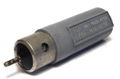
P6032_pwr.jpg|Internal view of power supply | P6032_pwr.jpg | Internal view of power supply connector. Signal coax passes through undisturbed. | ||
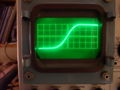
P6032_risetime.jpg|Display on [[545|545A]] with 1S1 and P6032. Pulse is generated by Tek [[284]] tunnel diode pulser driving into | P6032_risetime.jpg | Display on [[545|545A]] with 1S1 and P6032. Pulse is generated by Tek [[284]] tunnel diode pulser driving into 50 Ω load, GR-BNC adaptor and then to the probe using a probe to BNC adaptor. The 10x attenuator tip was used on the P6032. Timebase is 200 ps/div. | ||
Tek p6032 kit 1.jpg | Tek p6032 kit 1.jpg | ||
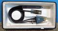
Tek p6032 kit 2.jpg | Tek p6032 kit 2.jpg | ||
| Line 32: | Line 61: | ||
</gallery> | </gallery> | ||
{{Parts|P6032}} | |||
[[Category:Active | [[Category:Active oscilloscope probes]] | ||
Latest revision as of 04:56, 27 October 2023

The Tektronix P6032 is an 850 MHz cathode-follower probe, intended for use with samplers such as the 1S1, 3S1, 3S76, 4S1, and 4S2. It was designed by Murlan Kaufman.
There is an EC1000 subminiature triode in the probe body, which is why it gets slightly warm during operation.
Like all active probes, the P6032 requires power, and for this reason it has two connectors at the scope end of the cable. There is a four-pin power connector and a 50 Ω GR-874 connector for the signal.
The triode has limited dynamic range, so attenuator attachments are provided that attach to the tip of the probe. These attenuators also reduce the loading of the probe on the probed circuit.
Key Specifications
| Bandwidth | ≥850 MHz |
|---|---|
| Rise time | 0.4 ns max. |
| Attenuation | 10× to 1000× in 1-2-5 steps with supplied attenuator heads, 3× without attenuator |
| Dynamic range | ±0.15 V × attenuation |
| Maximum input voltage | ±0.225 V × attenuation, de-rated for CW operation for 500× and 1000× attenuator heads |
| Input resistance | 10 MΩ with any attenuator head, 3 MΩ without attenuator head |
| Input capacitance | 3.6 pF (10× head) to 1.3 pF (1000× head), 7 pF without attenuator head |
| Output impedance | not specified, calibrated for 50 Ω load |
| DC offset | ≈0.5 V (not adjustable) |
Internals
The body of the probe contains a clipping line composed of what appears to be 21 mm of RG-174 coax connected to the triode's cathode at one end and open at the other end. The circuit description in the manual describes it vaguely, saying only that, "The clipping line reduces signal aberration to a minimum." Page 40 of the Tektronix Probe Circuits concept book explains in more depth,
The section of 50 Ω coax tied to V1 cathode damps ringing in the high frequency response. The coax is terminated in an open circuit to reflect a short circuit 1/4 wavelength from the termination. Since voltage does not exist at a short circuit, the ringing is damped.
The "V1" in the preceding excerpt refers to V103 in the P6032.
Pictures
-
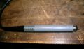
External view of P6032 without attenuator attachment
-
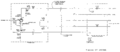
P6032 Schematic
-
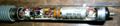
Internal view of P6032 Probe tip connects directly to triode grid, which is a bare wire coming out of the top of the tube. Clipping line runs along the body of the probe to the left of the tube socket.
-
×20 attenuator tip
-

Internal view of power supply connector. Signal coax passes through undisturbed.
-
-
-
-

-


Some Parts Used in the P6032
| Part | Part Number(s) | Class | Description | Used in |
|---|---|---|---|---|
| EC1000 | Vacuum Tube (Triode) | subminiature triode | P6025 • P6032 |