1A1
The Tektronix Type 1A1 plug-in for the 500-series scopes has two channels and a −3 dB point of 50 MHz at 50 mV/Div, 28 MHz at 5 mV/Div, and 2 Hz to 15 MHz at 500 μV/Div when channels 1 and 2 are cascaded. It was designed by Ron Olson.

There were three distinct versions of 1A1.
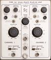
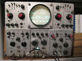
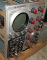
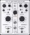
- The first version, from 1964 to 1966, has a Nuvistor front-end, and rotary input switches that were concentric with the BNC jacks. The knobs to invert the input channels are concentric with the vertical position knobs.
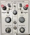
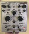
- The second version, from 1966 to ??? has fluted round V/cm knobs, and lever switches. The channel inversion control is an organ-style pull-push knob. The nuvistors are mounted under a thermal cover on a sub-chassis with rubber stand-offs.
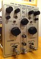
- The third model, from ??? until the end has four-sided V/cm knobs and a FET front-end.
Type 1A1 uses the "ALT SWEEP SLAVE PULSE" signal that is sent by scopes on pin 7 of the plug-in connector. In a Type 547 mainframe, this signal allows channel 1 to be displayed using the "A" timebase and channel 2 using the "B" timebase. This is useful, for example, to view the IF and AF of a radio receiver at the same time. Even after the front-end transitioned from Nuvistors to FETs, the output amplifier continued to use Nuvistors.
Type 1A1 has an External Trigger output for mainframes prior to the 547 that don't support plug-in triggering, and supplies the trigger system on pins 4/5 of the mainframe interface. It also has a ×10 amplified output from channel 1 that can be cascaded into the channel 2 input for 500 μV/Div sensitivity at reduced bandwidth (15 MHz).
Types 1A1 and 1A2 were introduced together in 1964, the former for high-end use, the latter as an upgrade/replacement for Type CA. Both remained available until the 500-series scope line was discontinued.
The 1A1 is not a perfect superset of the 1A2; it supplies external trigger from channel 1 only.
The 1A1 may have evolved from the Type J, which never went into production.
Key Specifications
| Bandwidth | 50 MHz @ 50 mV/Div and up (in fast mainframes), 28 MHz @ 5 mV/Div, 15 MHz with cascaded channels (~0.5 mV/Div) |
|---|---|
| Rise time | 7 ns @ 50 mV/Div and up (in fast mainframes), 13 ns @ 5 mV/Div, 24 ns with cascaded channels (~0.5 mV/Div) |
| Deflection | 5 mV/Div to 20 V/Div, 1−2−5 |
| Max. input | 600 V DC + peak AC |
| Input impedance | 1 MΩ // 15 pF |
| Modes | Ch 1, Ch 2, ALT, CHOP, ADD |
Links
Documents Referencing 1A1
| Document | Class | Title | Authors | Year | Links |
|---|---|---|---|---|---|
| Martzloff High-speed Recording System.pdf | Article | High-Speed Transient Recording System | François Martzloff | 1968 | 544 • 1A1 |
Pictures
-
1A1 SN121
-
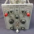
Early 1A1
-
Second 1A1 version
-
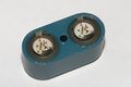
left: Nuvistor right: FET
-
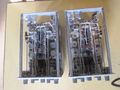
left: Nuvistor right: FET
-
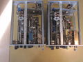
left: Nuvistor right: FET
-
Nuvistors under thermal cover, on shock-mounted sub-chassis
-
Nuvistor cover and tubes unplugged
-
Nuvistor cover and tubes, bottom
-
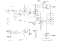
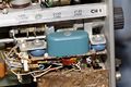
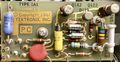
Early 1A1 front end
-
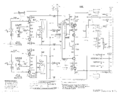
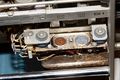
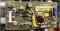
Late 1A1 Output Amp
-
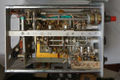
Early 1A1 Left View
-
Latest version of 1A1
-
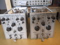
556 with second version 1A1 in left bay and first version 1A1 in right bay.
-
Black 1A1
-
Latest version 1A1. Photo courtesy of Dan Wilson (Hideaway Studio).
-
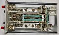
1A1 - First Version - Top
-
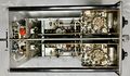
1A1 - First Version - Underside
-
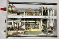
1A1 - First Version - RHS
-
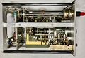
1A1 - First Version - LHS
-
Input FET board CH1
-
Input FET board CH2
-


Components
Some Parts Used in the 1A1
| Part | Part Number(s) | Class | Description | Used in |
|---|---|---|---|---|
| 7586 | 154-0306-00 | Vacuum Tube (Triode) | Nuvistor triode | M • 1A1 • 1A2 • 1A5 • 10A2 • 10A2A • 11B1 • 11B2A • 321 • 321A • 3A1 • 3A1S • 3A3 • 3A5 • 3A6 • 3A7 • 3A8 • 3A74 • 3S76 • 3T77 • 3T77A • 3B5 • 4S1 • 4S2 • 6R1 • 6R1A • 9A1 • 9A2 • 82 • 86 • S-311 |