2712

The Tektronix 2712 is a spectrum analyzer with a frequency range of 9 kHz to 1.8 GHz. The minimum resolution bandwidth is 3 kHz, and provides measurement resolution proportional to the frequency accuracy or span. With non-volatile memory (NVRAM) at 124 kB can save up to 108 displays of waveforms and markers, and up to 36 front panel setups, large user-defined key programs, and antenna factor tables.
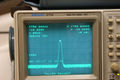
The single and delta markers provide direct readout of frequency and amplitude information of any point along any displayed trace. Or, get the relative (delta) frequency and amplitude information between any two points along any displayed trace or between traces.
True analog display capability, along with fast sweep speeds and TV Line and TV Field triggering provide demodulation of video carriers for making depth-of-modulation checks or looking at special baseband data, VITS, and other signals. An internal audio amplifier and AM/FM detectors let one hear demodulated signals, using either the build-in speaker or headphone jack for signal identification and troubleshooting and in communications applications.
Additional features include Digital Storage Display (selectable acquisition modes of positive peak only, positive/negative peak, Max hold, Waterfall, and an analog sweep when digital storage is off), Ensemble Averaging, Internal Preamp, Internal Calibrator (accessed through Input Menu), Alternate Reference Level Units (dBm, dBmV, dBV, dBµV, dBµW, and dBµV/m), User-Definable Power-on Status, Center Measure, Graticule Illumination (for CRT photography), and Direct Plot/Print (Printers via Opt. 03 GPIB, or RS-232-C interface via Opt. 08).
Front panel inputs/outputs are: RF INPUT N connector (50Ω, +20 dBm Max, 100 V DC blocking capacitor); and GEN N connector (50Ω, 0 to -48 dBm, Opt. 4 Tracking Generator generates a sweep frequency to enable the Spectrum Analyzer to make circuit response measurements, i.e. scalar network analysis).
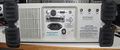
Rear panel inputs/outputs are: J101 SMA connector (Female SMA installed for Opt. 15), J102 EXT TRIG BNC connector (10 kΩ, 50V (DC + peak AC)), J103 DB9 connector (Not RS-232 compatible. Accessory connector: Pin 1 Video Input, Pin 2 Ground, Pin 3 Video Output, Pin 6 Sweep Gate, Pin 7 Sweep Output, all others unused), J104 GPIB connector (IEEE Std 488 connector) or Opt. 08: RS-232 interface (Digital Communication Port.).
Key Specifications
| Frequency | 9 kHz to 1.8 GHz |
|---|---|
| Frequency Span (plus 0 Hz and MAX: 180 MHz/div) | 1 kHz/div to 100 MHz/div in 1, 2, 5 sequence |
| Resolution Bandwidth | -6 dB bandwidth selections are 3 kHz, 30 kHz, 300 kHz, and 5 MHz ; Down to 300 Hz with Opt. 01 |
| RF Input impedance | 50 Ω |
| Maximum Safe Input Power | +20 dBm (0.1 W or 2.2 V) continuous peak, ≤100 V DC blocking capacitor |
| RF Attenuator | 0 dB to 50 dB, 2 dB steps |
| Sensitivity | -117 dBm at 3 kHz RBW, -129 dBm at 3 kHz RBW w/preamp |
| Reference Level Range | -70 dBm to +20 dBm; -23 dBmV to +66.9 dBmV |
| Sweep Speed | 2 sec/Div to 1 µs/Div in 1, 2, 5 sequence |
| Triggering Modes | Free Run, Internal, External, Line, TV Line, and TV Field |
| Displayed Average Noise | −66 dBm to −100 dBm |
| Display Dynamic Range | 80 dB |
| Dynamic Range | ≥100 dBm |
| Internal Calibrator | 100 MHz marker at -30 dBm |
| Included Accessories | Operator’s Manual; Power Cord; Front Cover; Adapter 50 Ω N Male to BNC Female, 75 Ω to 50 Ω Minimum Loss Attenuator N Male to BNC Female |
| Weight | Standard accessories: 11.25 kg (<25 lbs); Basic configuration: 10.2 kg (22.5 lbs) |
| Power | 90 − 132 VAC, 48 to 440 Hz; 90 – 250 VAC, 47 to 63 Hz. At 115 VAC, 60 Hz, 90 W (standard), 105 W max (with options) |
| Operating Atmospherics | Temperatures: 0 °C to +50 °C; Humidity: MIL-T-28800E; Altitude: Up to 4.6 km (15,000 ft) |
Options
- Opt. 01: 300 Hz Resolution Bandwidth filter; Phase-lock with span/div ≤20 kHz
- Opt. 02: Frequency Counter, 1 Hz or 1 kHz, menu selectable
- Opt. 03: GPIB Interface (cannot be combined with Opt. 09)
- Opt. 04: TG Tracking Generator, 100 kHz to 1.8 GHz (cannot be combined with Opt. 12 or 14)
- Opt. 06: Battery Power Option (2704 Inverter and 2705 Battery Pack)
- Opt. 08: Replace GPIB with RS-232-C (cannot be combined with Opt. 03)
- Opt. 09: Centronix interface (cannot be combined with Opt. 03)
- Opt. 10: Video Monitor mode
- Opt. 11: Non-volatile RAM storage for setups, displays, and user-definable key sequences
- Opt. 12: Quasi-peak detector and additional RBW filters (cannot be combined with Opt. 04 or 14)
- Opt. 14: Adds Resolution Bandwidths of 1 kHz, 10 kHz, 100 kHz, and 1 MHz (cannot be combined with Opt. 04 or 12)
- Opt. 15: Tek 1405 TV Sideband Adapter interface installed at J101 as SMA female
- Opt. 20: EMC antenna set plus tripod and coax suitable for tests to 1 GHz
- Opt. 30: Rackmount
- Opt. 33: Travel Line Package
- Opt. 34: Portable to Rackmount Adapter.
See also the 2706 preselector and 2707 tracking generator.
Pictures
-
-
-
-
-
-
-

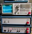
2712 with 2706
-


